


Hardware and Software Design • Manufacturing Services
P a g e 18
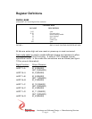
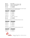
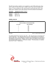
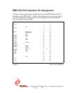
Parallel termination resistors are supplied on each differential pair along
with a switch to allow the user to select which lines are terminated and
where. In some systems it will make sense to terminate the lines in the
cable and in others it will make sense to use the onboard terminations.
CONTROL CORRESPONDING IO BITS
TERM0 IO_0..7
TERM1 IO_8..11
TERM2 IO_12..13
TERM3 IO_14..15
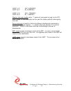
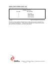
PMC4U_SW_IN
[0X14] PMC-4U User Switch Port read only
USER CONTROL SWITCH REGISTER
DATA BIT DESCRIPTION
5 UB5
4 UB4
3 UB3
2 UB2
1 UB1
0 UB0
FIGURE 8 PMC-4U SWITCH READ BIT MAP
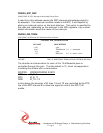
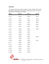
The Switch Read Port has the user bits. The user bits are connected to 6
switch positions. The switches allow custom configurations to be defined
by the user and for the software to “know” how to configure the read/write
capabilities of each IO line. Please note that the lower 6 bits of the switch
are implemented [positions 7 & 8 are unused]. The silk-screen is marked
with the ‘0’ and ‘1’ definitions.