


Hardware and Software Design • Manufacturing Services
P a g e 14
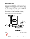
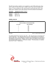
SCC Tx A OUT_4 (188)
SCC Rx A AUX_IN_0 (enhanced hysteresis 188)
SCC Rx Clk AUX_IN_1 (enhanced hysteresis 188)
SCC RTS A AUX_OUT_0 (open drain)
SCC Tx B IO_15 (RS422)
SCC Rx B IO_13 (RS422)
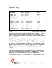
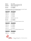
When test mode select is “10” the following changes are made (if a signal
is not listed here, its connection remains the same):
Signal Function Driver/Receiver
UART Rx A IO_1 (RS422)
UART Rx B IO_3 (RS422)
UART Rx C IO_5 (RS422)
UART Rx D IO_7 (RS422)
SCC RTS A AUX_OUT_1 (open drain)
SCC Tx B IO_14 (RS422)
SCC Rx B IO_12 (RS422)
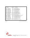
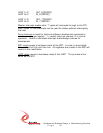
When test mode select is “11” the following changes are made:
Signal Function Driver/Receiver
UART Rx A IN_0 (RS232)
UART Rx B IN_1 (RS232)
UART Rx C IN_2 (RS232)
UART Rx D IN_3 (RS232)
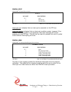
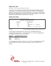
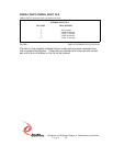
When test mode select is “01” the following changes are made:
Signal Function Driver/Receiver
UART Rx A IN_4 (RS232)
UART Rx B IN_5 (RS232)