


Chapter 1 Hardware Installation
27
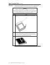
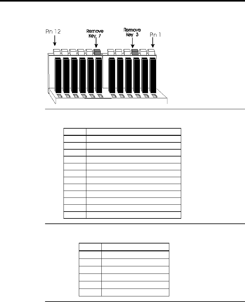
Step 6 Attach Cables, Continued
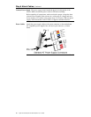
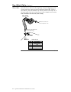
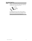
Connector Keys The keys on the connector must be cut to fit on some power supplies, as
shown below.
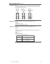
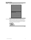
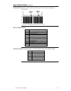
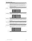
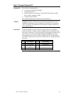
Power Connector Pinout
Pin Description
1 Power Good (Orange wire) (Not used)
2 VCC (Red wire)
3 +12 Volts (Yellow wire)
4 -12 Volts (Blue wire)
5 Ground (Black wire)
6 Ground (Black wire)
7 Ground (Black wire)
8 Ground (Black wire)
9 -5 Volts (White wire)
10 VCC (Red wire)
11 VCC (Red wire)
12 VCC (Red wire)
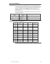
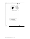
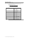
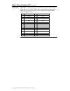
Keyboard CableThe keyboard attaches via a PS/2 keyboard connector, labeled AT_KB.
Pin Signal Description
1 Keyboard data
2 N/C
3 Ground
4 VCC
5 Keyboard clock
6 N/C
Cont’d