


39
6.0 UPS Monitoring
6.4 Computer Interface port
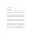
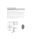
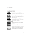
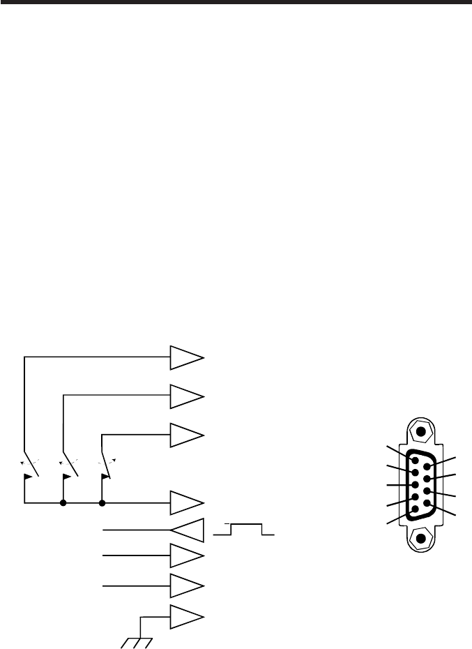
The Computer Interface port is shown below for your reference. Those with technical
abilities wishing to use this port in a special application should be aware of the
following limitations and capabilities of the interface.
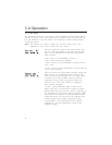
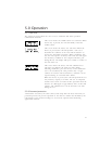
n Outputs at pins 3, 5, and 6 are open collector outputs which must be pulled up to
a common referenced supply no greater than +40 Vdc. The transistors are capable of
a maximum noninductive load of 25 mAdc. Use only Pin 4 as the common.
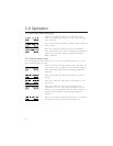
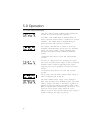
n The output at Pin 2 will generate a LO to HI RS-232 level upon transfer of the
output load to power derived from the UPSs battery. The pin is normally at a LO RS-
232 level.
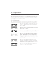
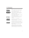
n The UPS will shut down when a HI RS-232 level, sustained for 4.5 sec., is applied
to Pin 1. The UPS responds to this signal, following a delay, only during mains
failures (on-battery operation).
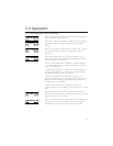
n An unregulated +24 Vdc appears at Pin 8 of the interface port whenever the UPS is
powered. The supply is limited to 40 mAdc maximum.
2
8
4
RS-232 Shut Down
Input
RS-232 Line Fail
Output
Unregulated
+24 Vdc Output
Chassis
Common
Normally Closed
Line Fail Signal
Normally Open
Low Battery Signa
l
Normally Open
Line Fail Signal
9
HI
4.5 s
1
6
3
5
6
7
8
9
1
2
3
4
5