


MX06 Power Plant User’s Manual Page 13
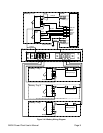
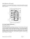
GMT Fuse protected Load Connections
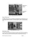
Connections for ¼ to 15 Amp DC loads require a ring terminal with a 0.170 in (4.3 mm)
clearance hole and are located at the rear of the unit. Load Connections should be made as
shown in Figure 3.7-2.
J2
J3
J5
J4
F3
F1
F5
F9
F7
F11
F2
F6
F4
F8
F12
F10
-54 V
54 V Rtn
Figure 3.7-2 Connections to GMT Fuses
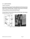
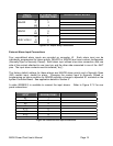
3.8. Input / Output Connections
Relay Output Connections
There are three output relays available that provide outputs via Form “C” relay contacts. Two of
these are pre-assigned as the Minor and Major relay outputs. The other output is designated
as “Very Low Voltage”. The relay contacts should only be used to switch resistive loads of 0.5
amperes or less at 60 Volts or less. Figure 3.8-1 shows the alarm output connection
designations. Whenever possible use the common and normally open contacts. If the alarm
wiring gets pulled loose, or the controller is removed, you will get an alarm. The output relays
energize when an alarm condition occurs. A cable (0W09050) is available to connect the output
relays. See Figure 3.7-2 for details.