


MX06 Power Plant User’s Manual Page 3
AC
DC
Control
AC
DC
Control
AC
DC
Control
AC
DC
Control
AC
DC
Control
J3
USER
ALARM
INPUTS
J2
ALARM
RELAY
OUTPUTS
J5
MOTORIZED
BREAKER
CONTROLS
J4
TEMPERATURE
PROBE
BATTERY (+)
BATTERY (–)
(orange)
(black)
UFA1
UFA2
UFA3
UFA4
1
2
3
4
5
6
7
8
9
10
-BAT
-BAT
-BAT
-BAT
1
2
3
4
5
6
7
8
9
MAJ NC
MAJ COM
MAJ NO
MIN NC
MIN COM
MIN NO
VLV NC
VLV COM
VLV NO
1
2
3
4
5
6
YELLOW
BROWN
BLACK
ORANGE
RED
BLUE
TMP
-BAT
+12 PWR
1
2
3
4
GND
L1 L2/N
GND
L1 L2/N
GND
L1 L2/N
One to 12 outputs
Visual Alarm
Load
Distribution
Module
CONTROL BUS
+BAT
-BAT
TRM1 TRM2
TRM3
TRM4 TRM5
TRM6
TRM7 TRM8
TRM9
M
Port
S
Port
Control Circuit
PC Board
AC
DC
Control
AC
DC
Control
AC
DC
Control
AC
DC
Control
AC
DC
Control
BATTERY (+)
BATTERY (–)
(orange)
(black)
GND
L1 L2/N
GND
L1 L2/N
GND
L1 L2/N
One to 12 outputs
Visual Alarm
Load
Distribution
Module
CONTROL BUS
TRM1 TRM2
TRM3
TRM4 TRM5
TRM6
TRM7 TRM8
TRM9
M
Port
S
Port
Main Power Distribution Backplane
Second Power Distribution Backplane
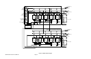
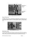
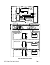
Figure 2.1-2 MX06 100 Block Diagram