


MX06 Power Plant User’s Manual Page 22
MX06 External Alarm Input Configuration
The MX06-50 and the MX06-100 alarm input circuitry is the same for both controllers. Refer to
board layouts in the preceding sections to identify switch 1. The four User Input Alarms can be
programmed for either a MAJOR or MINOR alarm upon activation and can be configured for
either a Normally Open (NO) or a Normally Closed (NC) input contact from the alarm source.
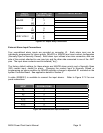
Set dipswitch S1 to program the User Input Alarms. Refer to Figure 5.2-1 for details. The
factory settings reflect normally open inputs (closed for alarm) with a MAJOR alarm priority for
each user alarm.
Alarm NO Setting NC Setting
Major
Setting
Minor
Setting
Factory
Setting
User 1 S1-1 Open S1-1 Closed S1-5 Open S1-5 Closed NO/Major
User 2 S1-2 Open S1-2 Closed S1-6 Open S1-6 Closed NO/Major
User 3 S1-3 Open S1-3 Closed S1-7 Open S1-7 Closed NO/Major
User 4 S1-4 Open S1-4 Closed S1-8 Open S1-8 Closed NO/Major
Figure 5.2-1 User Alarm Settings
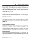
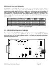
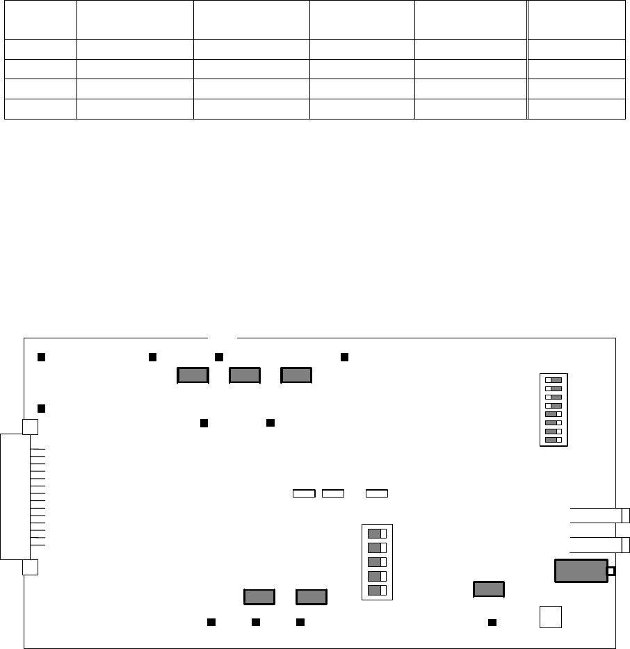
5.3. MX06-50 Configuration Settings
The control card for the MX06-50 is different than the control card for the MX06-100 due to
increased number of rectifiers in the MX06-100. The control card for the MX06 is the 0P9172
and for the MX06-100, the control card is the 0P9745. This section will deal with configurations
applicable to the MX06-50 only.
S2
1
RECT PRESENT
MAJ /MIN
SELECT
NO/NC INPUT
USER ALARMS
E13
E4
E8
E1
E9
E7
E2
E3 E11 E12 E10
S1
R31R30R14
R21R4
R56
V Adj
-BAT
+BAT
J2 J3 J5
J4
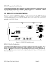
Figure 5.3-1 MX06-50 Controller Layout