


MX06 Power Plant User’s Manual Page 24
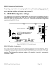
MX06-50 Temperature Probe Selection
Temperature compensation can be configured for either a Fahrenheit or Celsius probe by the
use of configuration jumpers on pin header J4 shown in Figure 5.3-1. The MX06-50 is factory
set for Fahrenheit operation, with jumpers on all position of J4.
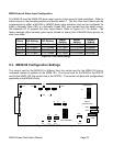
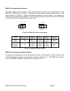
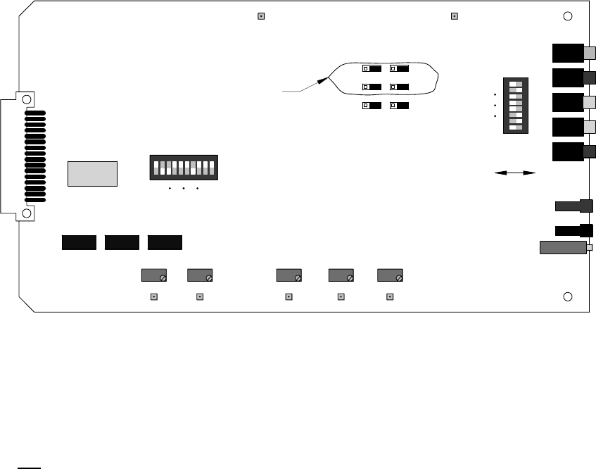
5.4. MX06-100 Configuration Settings
The control card for the MX06-50 is different than the control card for the MX06-100 due to
increased number of rectifiers in the MX06-100. The control card for the MX06 is the 0P9172
and for the MX06-100, the control card is the 0P9745. This section will deal with configurations
applicable to the MX06-100 only.
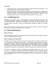
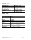
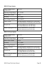
E101
E102
R101
DC GOOD
MAJOR
MINOR
LOW V
VLV
+BAT
-BAT
V ADJ
NO\NC
INPUT
USER ALM
MAJ/MIN
SELECT
ONOFF
1
8
J1
K1
K4 K2 K3
S2
RECT SELECT
ON: RECTIFIER NOT INSTALLED
OFF: RECTIFIER INSTALLED
110
RECT NUMBER
GMT ALMBATT ALM
J4
J5
J6
J7
J8
J9
(SEE MANUAL)
Factory Set. Do not touch.
RECON LEV ADJ
DISCON LEV ADJ
E12 E13
H V ALARM
L V ALARM
VLV ALARM
E9 E10 E11
R105 R106 R102
R103
E1
GND
R104
E8
V-ADJ
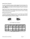
Figure 5.4-1 MX06-100 Controller Layout
MX06-100 Rectifier Configuration
The system Controller Board must know if a rectifier is present for each of the five slots. This is
done by the properly setting the dipswitch S2 (“RECT PRESENT”) on the Controller Board. If a
rectifier is not
present in a given slot, the corresponding switch position must be set to the “ON”
condition. The ON direction is labeled on the body of the dipswitch. Figure 5.4-1 locates switch
S2 on the PC board.