


MX28B600-48V
14
5.3.1 Cable Sizing Considerations
The battery cable(s) should be sized sufficiently large to limit the voltage drop from the
MX28B600 DC power plant to the battery during charging in accordance with system design
requirements. The cable(s) must also carry the full load current during battery operation. If
assistance is required to determine the necessary cables for the application, contact your sales
representative or APC DC Network Solutions Inc.
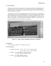
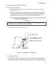
5.3.2 Connecting the Cables
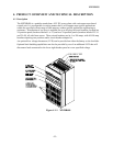
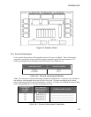
The battery cable connections are located at the center rear of the unit as shown in Figure 4.6-1.
The battery positive (return bus) and battery negative (-48V bus) buses each provide two sets of
threaded 3/8”-16 holes on one-inch centers for connecting two-hole battery cable lugs. Connect
the battery cables as applicable using 3/8”-16 bolts (not provided) and tighten them with a
torque wrench to 200 in-lbs.
***** CAUTION *****
Make certain that the battery polarity is correct when making connections to the
MX28B600 DC power plant. Incorrect connection could cause severe equipment damage.
5.4 DC SYSTEM GROUNDING
THE POSITIVE BATTERY CONNECTION (RETURN BUS) FOR THE POWER
PLANT MUST BE CONNECTED TO THE MASTER STATION GROUND. THE
RIGHT SIDE SECTION (when viewed from the front of the unit) OF THE RETURN BUS
PROVIDES A PAIR OF THREADED 3/8”-16 HOLES ON 1-INCH CENTERS FOR
CONNECTION OF A TWO-HOLE LUGGED CABLE TO THE MASTER STATION
GROUND. DETAILS FOR THIS CONNECTION SHOULD BE PROVIDED IN THE
SITE ELECTRICAL GROUNDING PLANS.
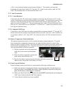
5.5 Rectifier Installation
The APC DC Network Solutions Inc. Model MRF28H54BV rectifiers are shipped in separate
containers. Follow the procedure below to install a rectifier.
1) Remove the rectifier from its shipping container.
2) Slide the rectifier into the shelf between the guides until it is fully seated.
3) Locate the rectifier retaining screws in the bag the manual came in.
4) Fasten the rectifier in place with the rectifier retaining screw.
Since all adjustments are made from the system control unit, no rectifier adjustments are
necessary.
NOTE: All “FLOAT” – “BOOST/EQUALISE” switches (one is located on the front of
each rectifier in the system) must be set to “FLOAT” to allow the MX28B600 to
control the output voltage properly.
5.6 Alarm Connections
The alarm connections for all rectifiers, breakers, and fuses are factory pre-wired. The
MX28B600 DC power plant, however, permits the user to program the system alarms in various
ways.