


MX28B600-48V
20
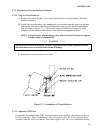
5.9.1 Apply AC Power
Turn on the circuit breakers that supply AC power to the rectifiers in the MX28B600 DC power
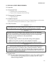
plant. The main screen should appear on the control unit display (see Figure 5.9-1). The display
on the control unit is a 2-lines by 16-characters display. The cursor cycles below the characters
of the active selection on the display. Information shown in the second line of Figure 5.9-1 that
extends beyond 16 characters (to the right of the “S” in “ALARMS”) can viewed on the control
unit display by using the scrolling controls (refer to Section 6 for operation of the control unit).
NOTE: When AC power is initially applied, there is a 60-second period during which no alarms
are reported.
MX28B600 +
STATUS ALARMS SYSTEM MODULES BATT PIN OEM
Figure 5.9-1
5.9.2 System Parameters Verification/Adjustment
The MX28B600 system control unit is delivered with pre-programmed parameter default
settings. A complete listing and description of all system configuration parameters as well as
displayable system status and information is provided in Section 6. Read Section 6 to gain an
understanding of and how to use the operational features provided by the MX28B600 DC power
plant. As a minimum, the following parameters should be verified and adjusted, if required,
before connecting batteries or loads to the power plant:
1) Battery Float Voltage - default = -54.00V DC (Check the manufacturer’s
recommendation for the batteries being used in the system.)
2) Battery Maximum Recharge Rate - default = 50A. (Bellcore specifications
recommend a maximum charging rate of capacity (in Ampere-hours) divided by 20
hours; check the battery manufacturer’s recommendation.)
3) System Voltage - measurement ≅ -54.00V DC (This is a measurement by the system of
the DC output bus voltage.)
4) LVD Option - default = “Enable” (If the MX28B600 does not have an LVD installed,
this should be changed to “Disable”.)
5) Rectifier Information - Check the rectifier information displays to verify that all
rectifiers installed can be viewed on the control unit display and that no rectifier alarms
are active.
Section 6 provides location information for these parameters and how to make changes if
required.
5.9.3 Full System Power Up
To complete a full system power up, perform the following steps
1) Turn OFF all the circuit breakers that supply AC power to the rectifiers in the
MX28B600 DC power plant.
2) Turn on the external circuit breaker from the battery to the power plant.