


MX28B600-48V
16
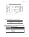
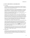
5.6.2 Alarm Outputs
There are eight alarms available that provide outputs via Form “C” relay contacts. The last two
of these are pre-assigned as the Minor and Major alarm outputs. The Major relay is energized
(NO-C contacts closed) during normal (non-alarm) operating conditions; all the other relays
energize when an alarm condition occurs. The other six outputs are initially designated as
“Relay 1” through “Relay 6” (the user may assign more meaningful names if desired). The
various system alarm conditions can be assigned to any of the eight alarm outputs.
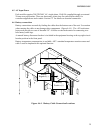
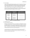
Table 5.6-3 shows the alarm output connection designations. Wago Connectors are located on
the interface card mounted in the top left side of the unit. The relay contacts should only be
used to switch resistive loads of 0.5 amperes or less at 60 volts or less.
ALARM
OUTPUT
TERMINAL
DESIGNATION
NO-NC-C
USER ALARM NOTES
RELAY #1
RELAY #2
RELAY #3
RELAY #4
RELAY #5
RELAY #6
MINOR
MAJOR
NO1-NC1-C1
NO2-NC2-C2
NO3-NC3-C3
NO4-NC4-C4
NO5-NC5-C5
NO6-NC6-C6
NO7-NC7-C7
NO8-NC8-C8
________________________
________________________
________________________
________________________
________________________
________________________
________________________
________________________
Table 5.6-3. Alarm Output Connections
5.7 Connecting The Loads
5.7.1 DC Circuit Breakers and Fuses
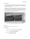
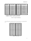
Both plug-in circuit breakers and GMT fuses can be installed in the MX28B600 power plant for
DC distribution circuit protection. Two plug-in circuit breaker tiers, consisting of a 24-position
panel (breakers labeled 1 to 24) and two 10-position panels (breakers labeled 25 to 34 and 39 to
48), provide 44 positions of -48V distribution. Available plug-in circuit breakers are shown in
table 5.7-1. Plug-in circuit breakers rated at 60A or more require two mounting positions and
require a breaker adapter kit, which is included (see kit selection information below the table).
The breaker adapter kit includes all necessary mounting hardware.
An optional load shed circuit is available. This option will disconnect any unessential loads
from the rest of the system. Loads hooked up to the lower left tier (CB 26-35) will be
disconnected. This will preserve the battery run time for essential loads. When hooking up the
loads, ensure that they are divided correctly.