


Customizing and Updating the PDU
60 kW InfraStruXure PDU — Operation and Configuration 55
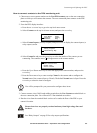
4. If the test was successful, place the Arm/Test switch back to the Arm position. The PDU
display interface will clear the EPO test mode alarm. If the test was not successful, see the
troubleshooting chart:
5. Repeat this test for each EPO switch installed.
6. Ensure that the Arm/Test rocker switch is in the Arm position on the monitoring unit.
Safety warnings
Hazardous voltage from the branch circuit must be isolated from the 24VAC, 24VDC, and contact
closure. 24VAC and 24VDC are considered Class 2 circuits as defined in Article 725 of the National
Electrical Code (NFPA 70) and Section 16 of the Canadian Electrical Code (C22.1).
A Class 2 circuit is a source having limited voltage and energy capacity as follows:
a. If an Inherently Limited Power Source, voltage and energy are limited to less than 30VAC,
less than 30VDC, and 8A.
b. If not an Inherently Limited Power Source, voltage and energy are limited to less than
30VAC, less than 60VDC, 250VA, and the current is limited to 1000/Vmax. The fuse is
limited to 5A if less than 20VAC or 20VDC, or 100/Vmaximum if less than 30VAC or
60VDC.
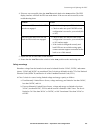
Problem Action
Neither state LED was red when EPO
switch was engaged.
• Check the wiring to your EPO switch.
• Check to make sure your EPO DIP switch
configuration is correct for your switch (NO
or NC).
Only one of the state LEDs was red
when the EPO switch was engaged.
• Check to make sure the EPO DIP switch
configuration is correct for your switch (NO
or NC) and test again.
• If the switch is configured correctly and
both LEDs are not red after testing again,
contact customer support at a number on the
back cover of this manual.