


54 60 kW InfraStruXure PDU — Operation and Configuration
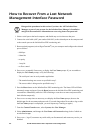
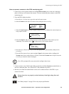
How to Test the EPO Switch
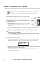
After a certified electrician has connected an EPO switch to the PDU
monitoring unit by way of the user connection plate, you can easily test
the switch to make sure it is wired and working properly. The
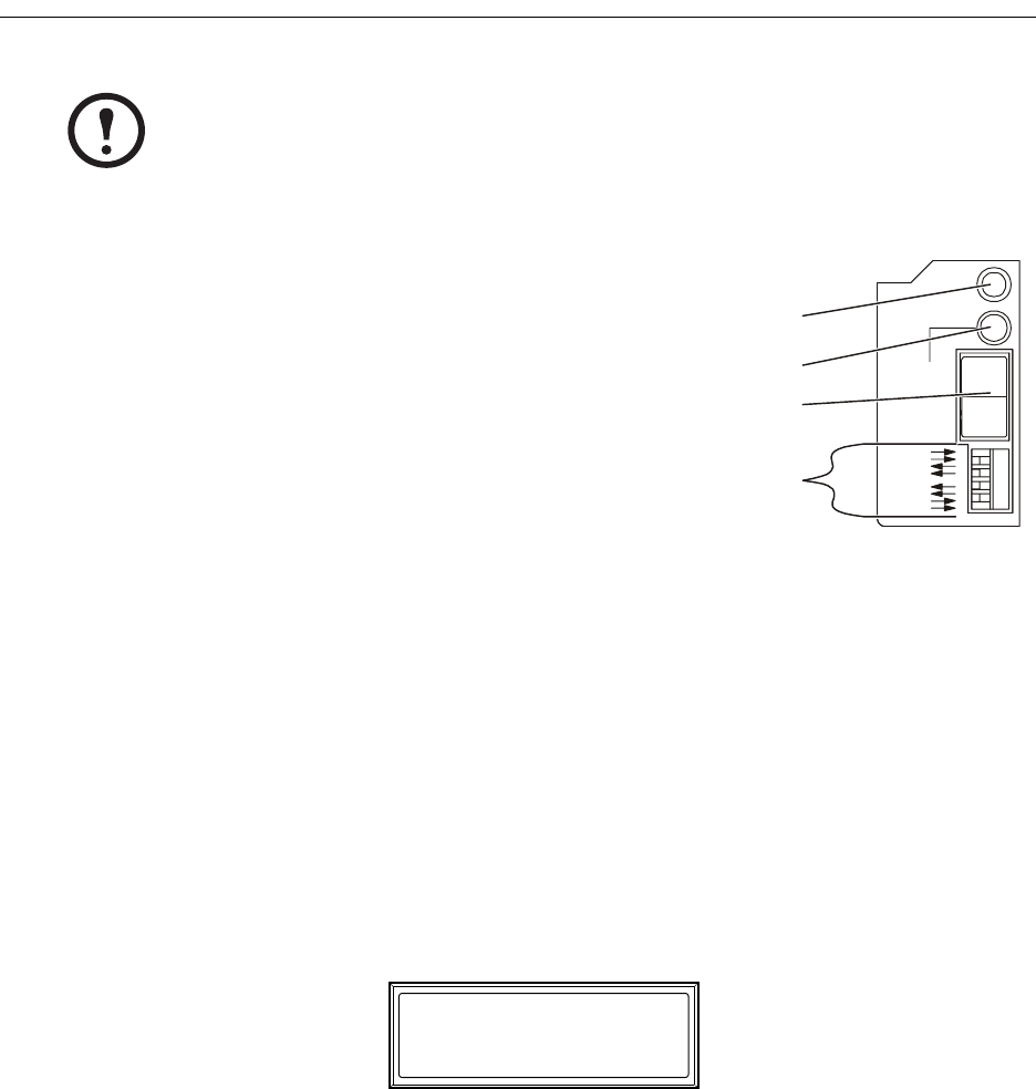
illustration to the right shows the EPO functions on the front panel of
the PDU monitoring unit.
To test your EPO wiring and switches:
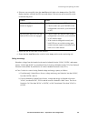
1. Place the Arm/Test switch in the Test position. The Armed LED will be dark and the PDU
display interface will show the following alarm (in addition to any other active alarms):
2. Engage the EPO switch. (If your switch is momentary, engage it with one person watching the
EPO state LEDs, and another at the EPO switch.)
3. Observe the EPO LEDs. If the switch is wired and working properly, when the switch is
engaged, the Tripped LED is red.
Note
APC offers an optional InfraStruXure EPO System (EPW9). Contact your APC sales
representative, or visit the APC Web site (www.apc.com) for more information.
EPO DIP switches configure the EPO input for the type of EPO
switch that is connected—Normally Open (NO) or Normally
Closed (NC).
When the EPO Arm/Test rocker is in the Test position, engaging the EPO switch will not
cause the load to be powered off. When the rocker is in the Armed position, engaging the
EPO switch will cause the PDU’s Main Input switch to be switched OFF.
The EPO Armed LED is green when the rocker is in the Armed position. The LED is dark
when the rocker is in the Test position.
The EPO Tripped LED is red when the EPO switch is engaged (the EPO button is pressed),
regardless of the state of the EPO Arm/Test rocker.
NO
NC
TRIPPED
ARMED
TEST
EPO
EPO Ready To Test
Active Alarm xxofxx