


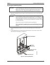
Chapter 2 Installing CoreModule 420 Options
12 QuickStart Guide CoreModule 420
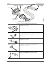
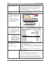
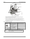
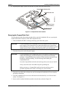
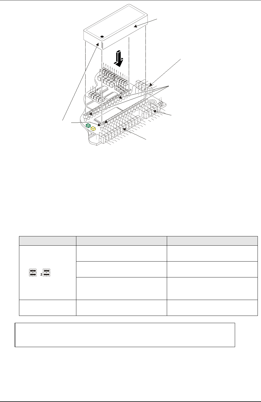
Bytewide
Socket (U5)
Pin 1
Serial Port (J3)
(COM 1)
Floppy/Parallel Port (J4)
Utility Connector (J5)
DiskOnChip Module
CM420QkS_04a
Figure 2-1. Installing DiskOnChip
3. Remove the DiskOnChip from the anti-static package and check it for bent pins, before
attempting to insert it into the bytewide socket (U5).
4. Align pin one of the bytewide socket (U5) with pin 1 of the DiskOnChip. See Figure 2-1.
5. Gently insert the DiskOnChip into the bytewide socket (U5) as shown in Figure 2-1 and gently
rock it side to side, while pressing down, until it is firmly into the bytewide socket (U5).
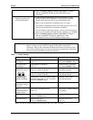
6. Set the jumpers for JP4, JP5, and JP7 to boot from the DiskOnChip before you restore power to
the CoreModule 420. See Table 2-1
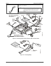
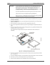
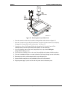
Table 2-1. DiskOnChip Jumper Settings
Jumper # Installed Removed
Enable BIOS – Normal operation;
boots from flash (Pins 1-3)
Disabled (See other positions)
Enable External BIOS – Used for
recovery (Pins 1-2)
Disabled (See other positions)
JP4 & JP5
BIOS Select
BIOS/DOC Select
Jumper Setting
(Shown in Default)
1
42
1
2
3
4
JP4JP5
Enable DOC – Boot from
DiskOnChip in bytewide socket
(Pins 1-3 & 2-4) Default
Disabled (See other positions)
JP7 DiskOnChip
Boot Address
Boot from DC000h-DDFFFh
(Pins 1-2)
Boot from CC000h- CDFFFh
(No jumper)
NOTE Refer to the CoreModule 420 Reference Manual for more information on
the location of the jumpers, as well as, other jumper settings. Refer also
to Table 1-1 in this manual.