


Chapter 1 Setting Up the EnCore 420
CoreModule 420 QuickStart Guide 3
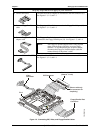
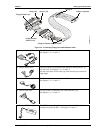
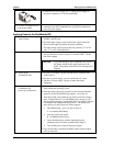
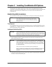
Connecting Cables to the CoreModule 420
Connect the cables provided with the CoreModule 420 QuickStart Kit to the respective connectors on
the CoreModule 420. Skip any cable(s) that do not apply to your situation.
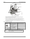
CM420QkS_03a
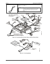
Utility (J5)
(Keyboard,
Mouse, Reset
Switch, etc.)
Serial 1
(COM 1)
(J3)
GPIO (J8)
Video (J11)
Floppy/
Parallel Port (J4)
IDE (J6)
Ethernet Port (J2)
Power (J7)
PC/104 Bus
USB (J10)
Serial 2 (J9)
(COM 2)
Serial 4 (J14)
(COM 4)
Serial 3 (J13)
(COM 3)
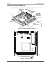
Figure 1-1. CoreModule 420 Connector Locations
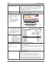
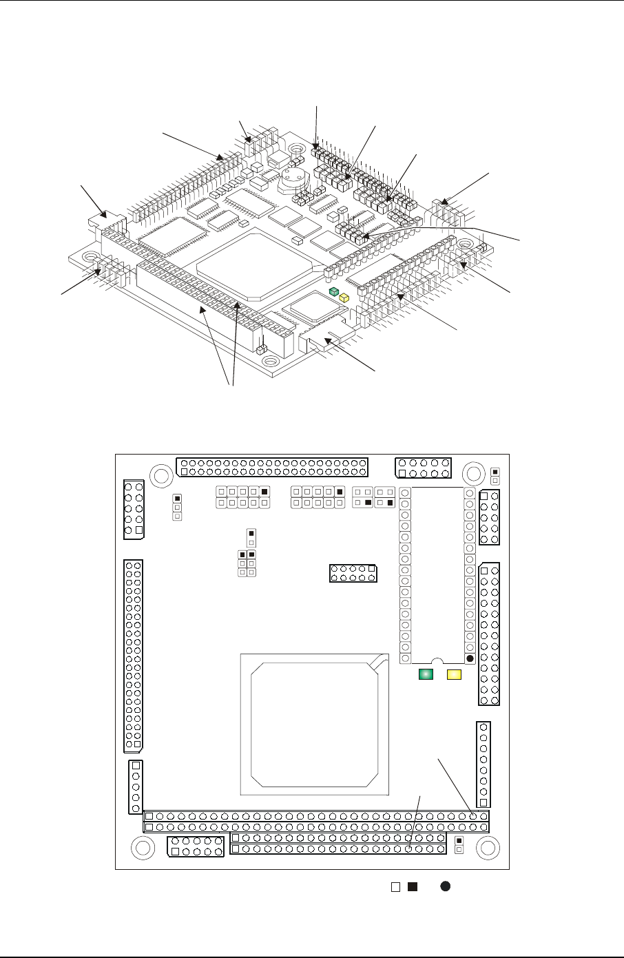
Pin 1 locations are marked with , , or
.
J9
J6
J11
J10
J7
J2
J4
J3
J5
P1B
P1A
P1C
P1D
JP2
J8
JP7
JP8
JP9
JP6
J13
J14
JP4JP5
9
10
10
4
3
1
2
1
2
U5
D1
D2
U14
JP1
CM420QkS_01e
Figure 1-2. Module Pin-1 Locations