


Chapter 1 Setting Up the CoreModule 420
4 QuickStart Guide CoreModule 420
Skip any steps that do not apply to your situation.
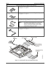
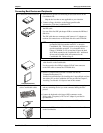
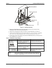
1) Connect IDE cable
The IDE cable and its adapter are connected to the IDE connector (J6).
See Figures 1-1, 1-2, and 1-3.
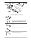
2) Connect Floppy/Parallel
cable
The floppy/parallel cable is connected to the Floppy/Parallel port (J4).
See Figures 1-1, 1-2, and 1-3.
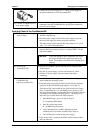
3) Connect Floppy-to-Parallel
adapter cable
The Floppy-to-Parallel adapter cable is connected to the cable
connected to the Floppy/Parallel port (J4). See Figures 1-3, and 1-4.
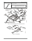
NOTE The Floppy-to-Parallel adapter cable is only required
when using the floppy disk drive to access floppy
diskettes. To use the parallel port for printer output,
disconnect the Floppy-to-Parallel adapter cable and
connect directly to the printer’s cable.
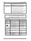
4) Connect Video cable (CRT)
The video cable (CRT) is connected to the Video connector (J11).
See Figures 1-1, 1-2, and 1-3.
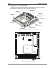
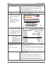
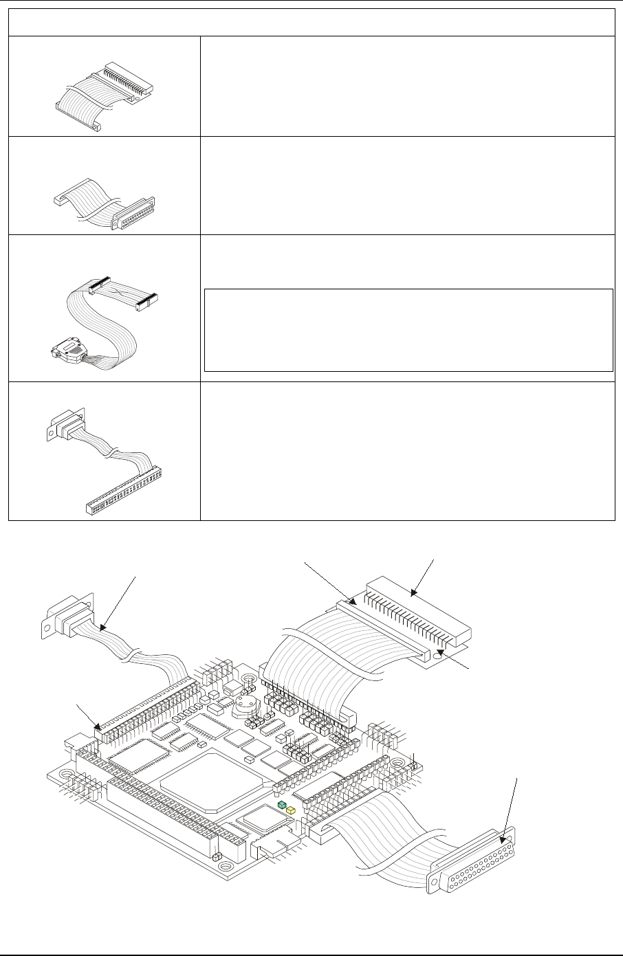
IDE Connector
Floppy/Parallel Port
Connector
Pin Adapter
(2mm to .1 inch)
Video
Connector
Pin 1
(Shown with only
one connector for
simplicity)
CM420QkS_08a
Figure 1-3. Connecting IDE, Video, and Floppy/Parallel Cables