


2-6
Jumper Summary
Ampro installs option jumpers in default positions so that in most cases the Little Board P6d
module requires no special jumpering for standard AT operation. You can connect the power and
peripherals and operate it immediately.
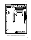
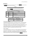
Jumper-pin arrays are designated W1, W2, and so forth. Jumper pins are spaced 2 mm apart. A
square solder pad identifies pin 1 of each jumper array. Table 2-2 is a summary of jumper use.
Factory settings are shown in the Default column. Some jumpers are set at the factory to configure
options that are not user-settable. These are indicated in the table. Do not change these settings.
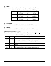
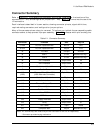
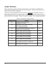
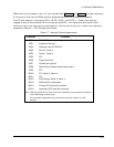
Table 2-2. Configuration Jumper Summary
Jumper Group Function Default
W1 CompactFlash IDE Master/Slave
ON=Master, OFF=Slave
ON
W2 BIOS Flash EPROM Programming Power
ON=Programming enabled
OFF= Programming disabled
ON
W3 External BIOS Board Enable/Cable Connection
ON=Normal, OFF=External Cable
ON
W4 Serial 1 RS485 100 Ohm Termination
ON=Terminated, OFF=Unterminated
OFF
W5 Serial 2 RS485 100 Ohm Termination
ON=Terminated, OFF=Unterminated
OFF
W6 Serial 3 RS485 100 Ohm Termination
ON=Terminated, OFF=Unterminated
OFF
W7 Serial 4 RS485 100 Ohm Termination
ON=Terminated, OFF=Unterminated
OFF
W8 Local Head Phone Enable
ON = Enable Local HP, OFF = Disable HP
OFF
W9 Watchdog timer reset enable
ON=Enabled, OFF=Disabled
OFF