


Little Board P6d Module
2-25
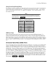
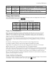
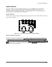
SELIN* Printer select input This bit is inverted and output to the pin. It selects a printer.
IRQE Interrupt request
enable
When set to 1, interrupts are enabled. An interrupt is generated by
the positive-going -ACK input.
PCD Parallel control
direction
When set to 1, port is in input mode. In printer mode, the printer is
always in output mode regardless of the state of this bit.
PD0-PD7 Parallel Data Bits
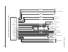
Floppy Disk Interface
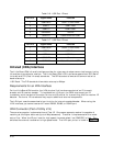
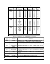
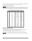
The on-board floppy disk controller and ROM BIOS support one or two floppy disk drives in any of
the standard DOS formats shown in Table 2-24.
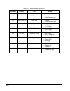
Table 2-24. Supported Floppy Formats
Capacity Drive Size Tracks Data Rate
360K 5-1/4 inch 40 250KHz
1.2M 5-1/4 inch 80 500KHz
720K 3-1/2 inch 80 250KHz
1.44M 3-1/2 inch 80 500KHz
Floppy Drive Considerations
Nearly any type of soft-sectored, single or double-sided, 40 or 80 track, 5-1/4 inch or 3-1/2 inch
floppy disk drive is usable with this interface. Using higher quality drives improves system
reliability. Here are some considerations about the selection, configuration, and connection of
floppy drives to the Little Board P6d module.
Drive Interface—The drives must be compatible with the board’s floppy disk signal interface, as
described below. Ampro recommends any standard PC-or AT-compatible 5-1/4 inch or 3-1/2 inch
floppy drive.
Drive Quality—Use high quality, DC servo, direct drive motor floppy disk drives.
Drive Select Jumpering—Both drives must be jumpered to the second drive select.
Floppy Cable—For systems with two drives, use a floppy cable with conductors 10-16 twisted
between the two drives. This is standard practice for PC-compatible systems.
Head Load Jumpering—When using drives with a Head Load option, jumper the drive for head load
with motor on rather than head load with drive select. This is the default for PC-compatible drives.
Drive Mounting—If you mount a floppy drive very close to the Little Board or another source of
EMI, you may need to place a thin metal shield between the disk drive and the device to reduce the
possibility of electromagnetic interference.
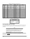
Floppy Interface Configuration
The floppy interface is configured using Setup to set the number and type of floppy drives connected
to the system. Refer to the Setup section starting on page 2–48 for details.