


Little Board P6d Module
2-41
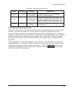
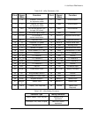
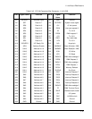
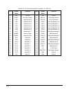
Table 2-38. Utility Connector (J19)
Pin # Signal
Name
Function Pin # Signal
Name
Function
1 -12 External -12V input
for expansion cards
2 GND Ground return
3 -5 External -5V input
for expansion cards
4 GND Ground return
5 LED LED current source (+5V
through 330 ohms)
6 RSVD No connection
7 SPKR+ PC audio signal output 8 GND Ground
9 RSTSW* To one side of
manual reset button.
10 KBDATA Keyboard serial data
11 KBCLK Keyboard clock 12 GND Keyboard ground
13 +5 Keyboard +5V power 14 MDATA Mouse serial data
15 MCLK Mouse clock 16 GND Mouse ground
17 +5 Mouse +5V power 18 IR_MODE IrDA Mode/IrDA RXB
19 IRTX IrDA Transmit /TTL TX2 20 IRRX IrDA Receive/TTL RX2
21 GND Ground 22 TTL_TX1 TTL Transmit 1
23 TTL_RX1 TTL Receive 1 24 GND Ground
25 TTL_TX3 TTL Transmit 3 26 TTL_RX3 TTL Receive 3
27 GND Ground 28 TTL_TX4 TTL Transmit 4
29 TTL_RX1 TTL Receive 4 30 GND Ground
31 KEY Key Pin 32 LID Lid Switch Input
33 PWRBTN
*
Power Button Input 34 BATLOW* Battery Low Input
35 RI* Ring Indicator Serial 2 36 GND Ground
37 SUSV Voltage for Power Down 38 GND Ground
39 SUSC* Suspend Status C 40 SMBCLK SMBus clock
41 SMBDAT
A
SMBus Data 42 SMBALRT* SMBus Alert
43 BATV + Battery (Not Required) 44 Ground - Battery (Not
Required)
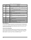
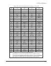
Table 2-39. Utility Mating Connector
Connector Type Mating Connector
Cable, Ribbon, 1mm, 44 pins 3M3625/44 or
equivalent
Connector, IDC, 2mm, 44 pins 3M87044-1000 or
equivalent