


2-22
Latch-Up Protection
The parallel port incorporates chip protection circuitry on some inputs, designed to minimize the
possibility of CMOS “latch up” due to a printer or other peripheral being powered up while the
Little Board P6d system is turned off.
Parallel Port Registers
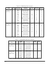
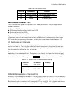
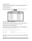
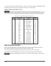
The low-level software interface to the parallel port consists of eight addressable registers. The
address map of these registers is shown in Table 2-21.
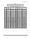
Table 2-21. Parallel Port Register Map
Register Name Address
Data Port Base address
Status Port Base address + 1
Control Port Base address + 2
EPP Address Port Base address + 3
EPP Data Port 0 Base address + 4
EPP Data Port 1 Base address + 5
EPP Data Port 2 Base address + 6
EPP Data Port 3 Base address + 7
Note: EPP registers are only accessible when in EPP mode
Standard and Bidirectional Operation
You can use the parallel port as a standard output-only printer port or as a PS/2-compatible
bidirectional data port with up to 12 output lines and 17 input lines. All data and interface control
signals are TTL-compatible. Set the parallel port’s default mode using Setup.
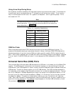
Using the Parallel Port in Bidirectional Mode
To use the port as a bidirectional data or digital control port you must set the default mode to
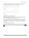
bidirectional in Setup or put it in bidirectional mode with a BIOS call. The following code example
shows how to set the parallel port mode to bidirectional.
;----------------------------------------------------------
; Code to set the parallel port mode to bidirectional
;----------------------------------------------------------
MOV AH,0CDh ; AMPRO command
MOV AL,0Ch ; AMPRO function
MOV BX,01h ; Extended mode (use 00 to set output-only mode)
INT 13h
Within bidirectional mode, the port can be in its input state or output state. The code shown above
leaves the port in its input state. An IN instruction of I/O address 378h reads the current state of
the data lines.