


2-42
LED Connection
To connect an external LED power-on indication lamp, connect the LED anode to pin-5 and the
cathode to ground. Pin 5 provides +5V through a 300 ohm resistor.
Speaker Connections
The board supplies about 100 mW for a speaker on pin-7. Connect the other side of the speaker to
ground (pin-8). A transistor amplifier buffers the speaker signal. Use a permanent magnet speaker
with an 8 ohm voice coil.
Push-button Reset Connection
Pin-9 provides a connection for an external normally-open momentary switch to manually reset the
system. Connect the other side of the switch to ground. The reset signal is “de-bounced” on the
board.
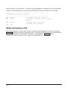
Keyboard Connection
You can connect an AT keyboard to the keyboard port. Normally, AT keyboards include a cable that
terminates in a male 5-pin DIN plug for connection to an AT (or a 6-pin miniature DIN plug for
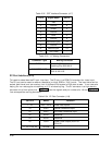
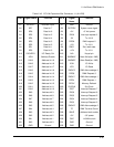
PS/2). Table 2-40 gives the keyboard connector pinout and signal definitions, and includes
corresponding pin numbers for DIN keyboard connectors.
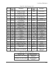
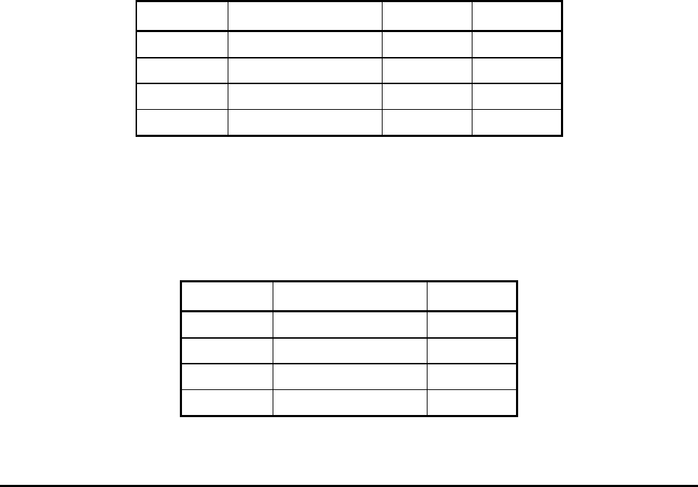
Table 2-40. Keyboard Connector (J19)
Pin # Signal Name DIN-5 Pins DIN-6 Pins
10 Keyboard Data 2 1
11 Keyboard Clock 1 5
12 Ground 4 3
13 Keyboard power 5 4
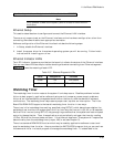
PS/2 Mouse Connection
You can connect aPS/2 Mouse to the mouse port. Normally, the PS/2 Mouse includes a cable that
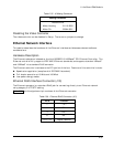
terminates in a 6-pin miniature DIN. Table 2-41 gives the keyboard connector pinout and signal
definitions, and includes corresponding pin numbers for DIN keyboard connectors.
Table 2-41. Keyboard Connector (J16)
Pin # Signal Name DIN-6 Pins
14 Mouse Data 1
15 Mouse Clock 5
16 Ground 3
17 Mouse power 4