


2-8
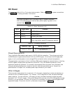
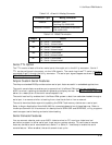
If a PCI expansion card requiring 3.3V is installed, that voltage can be connected to J10-5 to supply
power to J3, the PCI bus interface connector.
Switching Power Supplies
If you use a switching power supply, be sure it regulates properly with the load your system draws.
Some switching power supplies do not regulate properly unless they are loaded to some minimum
value. If this is the case with your supply, consult the manufacturer about additional loading, or
use another supply or another type of power source (such as a linear supply, batteries, etc.). The
minimum power for the Little Board P6d system appears in the power specifications in Chapter 1.
Powerfail NMI
The Little Board P6d module includes a circuit that can sense a power failure. If the +5V power
supply falls below ~4.7V, the powerfail logic produces a non-maskable interrupt (NMI).
When a NMI occurs, the BIOS detects the NMI and displays the message “Power Fail NMI” on the
console. At this point you have two options via the keyboard. You can mask the NMI and continue
(the PC architecture provides a mask bit for the non-maskable interrupt), or reboot the system.
If you want your system to respond to the NMI, you can provide a NMI handler in your application,
and patch the NMI interrupt vector address to point to your routine.
Backup Battery
The Real-Time Clock Battery on the Little Board P6d module should last 10 years under normal
usage.
Cooling Requirements
The Pentium-II CPU, DRAM module, video controller, and core logic chips draw most of the power
and generate most of the heat. The board is designed to support various speed versions of the
Pentium-II from 333MHz to 366MHz with a 66MHz clock speed.
A heat sink and fan are provided for the CPU and a thermal sensor is used to monitor the CPU
temperature, as described below.
Thermal Sensor
A thermal sensor monitors the internal temperature of the Pentium-II CPU. If the thermal sensor
detects the CPU temperature has exceeded its upper temperature threshold (100°C/212°F), the
thermal sensor’s logic sends a signal to the BIOS to reduce the CPU clock speed. This speed
reduction remains in effect until the processor has cooled to the lower sensor limit. Choosing to
operate the CPU at a temperature higher than this upper limit should be avoided due to the
possibility of CPU damage and its erratic operating speed.