


ADSP-BF538F EZ-KIT Lite Evaluation System Manual 1-11
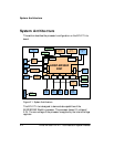
Using ADSP-BF538F EZ-KIT Lite
Example code is provided in the EZ-KIT Lite installation directory to
demonstrate how to program flash memory.
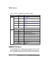
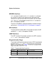
Table 1-4 shows a sample value for the asynchronous memory configura-
tion register,
EBIU_AMBCTL0.
CAN Interface
The Controller Area Network interface contains a Philips TJA1041
high-speed CAN transceiver. The PD9 programmable flag connects to the
error and power-on indication output (ERR). The PC1 of the processor con-
nects to the receive data output (RXD), and PCO connects to the transmit
data input (TXD).
The CAN interface can be disconnected from the processor by turning
positions 1 though 4 of the SW2 switch OFF. When in the OFF position, the
signals can be used elsewhere on the board. See “CAN Enable Switch
(SW2)” on page 2-10 for more information.
The CAN interface contains two 4-position modular connectors (see
“CAN Connectors (J5 and J11)” on page 2-21).
Example programs are included in the EZ-KIT Lite installation directory
to demonstrate CAN circuit operation.
Table 1-4. Asynchronous Memory Control Register Setting Example
Register Value Function
EBIU_AMBCTL0 0x7BB07BB0 Timing control for banks 1 and 0