


ADSP-BF538F EZ-KIT Lite Evaluation System Manual 2-19
ADSP-BF538F EZ-KIT Lite Hardware Reference
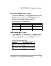
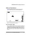
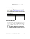
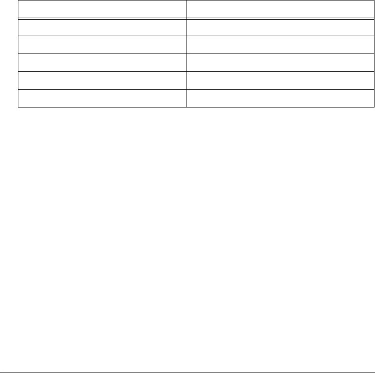
User LEDs (LED2–6)
Five LEDs connect to five general-purpose IO pins of the processor (see
Table 2-15). The LEDs are active high and are lit by writing a 1 to the
correct PC signal. Refer to “LEDs and Push Buttons” on page 1-13 for
more information about how to use flash memory when programming the
LEDs.
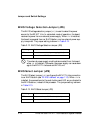
USB Monitor LED (ZLED3)
The USB monitor LED (ZLED3) indicates that USB communication has
been initialized successfully, and you can connect to the processor using a
VisualDSP++ EZ-KIT Lite session. This takes approximately 15 seconds.
If the LED does not light, try cycling power on the board and/or
re-installing the USB driver (see the VisualDSP++ Installation Quick Refer-
ence Card).
L
When VisualDSP++ is actively communicating with the EZ-KIT
Lite target board, the LED can flicker, indicating communications
handshake.
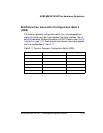
Table 2-15. User LEDs
LED Reference Designator Processor Programmable Flag Pin
LED2 PC5
LED3 PC6
LED4 PC7
LED5 PC8
LED6 PC9