


ADSP-BF538F EZ-KIT Lite Evaluation System Manual 2-13
ADSP-BF538F EZ-KIT Lite Hardware Reference
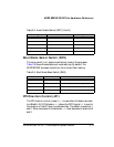
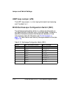
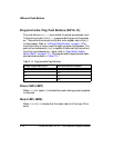
Boot Mode Select Switch (SW3)
The rotary switch (SW3) determines the boot mode of the processor.
Table 2-9 shows the available boot mode settings. By default, the
ADSP-BF538F processor boots from the on-board flash memory.
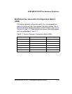
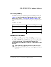
PPI Direction Control (JP1)
The PPI direction control jumper (JP1) is used when the board connects
to a Blackfin AV EZ-Extender. JP1 allows the GPIO signal PD7 to control
the direction of the PPI bus via a software flag. The default is positions 1
and 2. When connected to the extender, JP1 must be placed in positions 2
and 3.
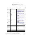
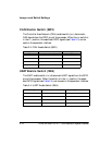
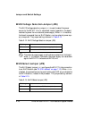
TSCLK0 4 (ON) TSCLK0
TFS0 5 (ON) TFS0
Clock loopback 6 (ON) NU
FS loopback 7 (ON) NU
ADC master/slave 8 (ON) NU
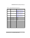
Table 2-9. Boot Mode Select Switch (SW3)
SW3 Position 1 SW3 Position 2 Processor Boot Mode
ON ON Execute from 16-bit external memory
ON OFF Boot from 16-bit flash memory (default)
OFF ON Boot from SPI serial master
OFF OFF Boot from SPI serial slave
Table 2-8. Audio Enable Switch (SW7) (Cont’d)
EZ-KIT Lite Signal SW7 Switch Position (Default) Processor Signal