


Jumper and Switch Settings
2-10 ADSP-BF538F EZ-KIT Lite Evaluation System Manual
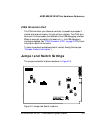
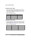
CAN Enable Switch (SW2)
The Controller Area Network (CAN) enable switch (SW2) disconnects
CAN signals from the GPIO pins of the processor. When the SW2 switch is
in the OFF position, the associated GPIO signals (see Table 2-3) can be
used on the expansion interface.
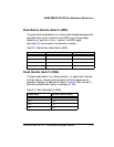
UART Enable Switch (SW4)
The UART enable switch (SW4) disconnects UART signals from the GPIO
pins of the processor. When the switch is in the OFF position, the associ-
ated GPIO signals (see Table 2-4) can be used on the expansion interface.
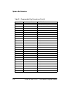
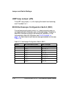
Table 2-3. CAN Enable Switch (SW2)
CAN Signal SW2 Switch Position (Default) Processor Signal
ENABLE 1 (ON) NU
STANDBY 2 (ON) NU
ERROR 3 (ON) PD9
RECEIVE DATA 4 (ON) PC1
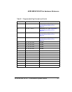
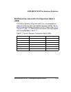
Table 2-4. UART Enable Switch (SW4)
EZ-KIT Lite Signal SW4 Switch Position (Default) Processor Signal
CTS 1 (ON) PC0
RX0 2 (ON) NU
RTS 3 (ON) PC1
LOOPBACK 4 (OFF) NU