


REV. 0
AD9883A
–14–
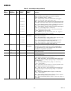
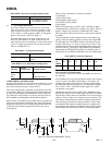
Table VI. Control Register Map (continued)
Write and
Hex Read or Default Register
Address Read Only Bits Value Name Function
0FH R/W 7:1 0******* Bit 7 – Clamp Function. Chooses between HSYNC for Clamp
signal or another external signal to be used for clamping.
(Logic 0 = HSYNC, Logic 1 = Clamp.)
*1****** Bit 6 – Clamp Polarity. Valid only with external Clamp signal.
(Logic 0 = active high, Logic 1 select active low.)
**0***** Bit 5 – Coast Select. Logic 0 selects the coast input pins to be used
for the PLL coast. Logic 1 selects Vsync to be used for the PLL coast.
***0**** Bit 4 – Coast Polarity Override. (Logic 0 = Polarity determined by
chip, Logic 1 = Polarity set by Bit 3 in register 0Fh.)
****1*** Bit 3 – Coast Polarity. Changes polarity of external COAST signal.
(Logic = 0 = active high, Logic 1 = active low.)
*****1** Bit 2 – Seek Mode Override. (Logic 1 = allow low-power mode,
Logic 0 = disallow low-power mode.)
******1* Bit 1 – PWRDN. Full Chip Power Down, active low. (Logic 0 =
Full Chip Power-Down, Logic 1 = normal.)
10H R/W 7:3 10111*** Sync-on-Green Sync-on-Green Threshold – Sets the voltage level of the Sync-on-
Threshold Green slicer’s comparator.
*****0** Bit 2 – Red Clamp Select – Logic 0 selects clamp to ground. Logic
1 selects clamp to midscale (voltage at Pin 37).
******0* Bit 1 – Green Clamp Select – Logic 0 selects clamp to ground.
Logic 1 selects clamp to midscale (voltage at Pin 37).
*******0 Bit 0 – Blue Clamp Select – Logic 0 selects clamp to ground.
Logic 1 selects clamp to midscale (voltage at Pin 37).
11H R/W 7:0 00100000 Sync Separator Sync Separator Threshold – Sets how many internal 5 MHz clock
Threshold periods the sync separator will count to before toggling high or
low. This should be set to some number greater than the maxi-
mum Hsync or equalization pulsewidth.
12H R/W 7:0 00000000 Pre-Coast Pre-Coast – Sets the number of Hsync periods that coast becomes
active prior to Vsync.
13H R/W 7:0 00000000 Post-Coast Post-Coast – Sets the number of Hsync periods that coast stays
active following Vsync.
14H RO 7:0 Sync Detect Bit 7 – Hsync detect. It is set to Logic 1 if Hsync is present on the
analog interface; otherwise it is set to Logic 0.
Bit 6 – AHS: Active Hsync. This bit indicates which analog Hsync
is being used. (Logic 0 = Hsync input pin, Logic 1 = Hsync from
Sync-on-Green.)
Bit 5 – Input Hsync Polarity Detect. (Logic 0 = Active Low,
Logic 1 = Active High.)
Bit 4 – Vsync detect. It is set to Logic 1 if V-sync is present on the
analog interface; otherwise it is set to Logic 0.
Bit 3 – AVS: Active Vsync. This bit indicates which analog Vsync
is being used. (Logic 0 = Vsync input pin, Logic 1 = Vsync from
sync separator.)
Bit 2 – Output Vsync Polarity Detect. (Logic 0 = Active Low,
Logic 1 = Active High.)
Bit 1 – Sync-on-Green detect. It is set to Logic 1 if sync is present
on the green video input; otherwise it is set to 0.
Bit 0 – Input Coast Polarity Detect. (Logic 0 = active low, Logic 1 =
active high.)