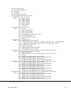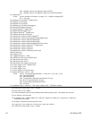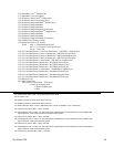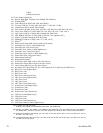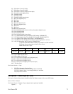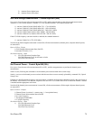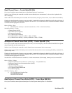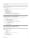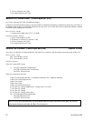
Site Master Returns: 17 bytes
1-2) Battery Status flags ( Refer to Smart Battery Data Spec 5.1.2.1)
3-4) State of Charge (unsigned integer 0 to 100(%)Full)
5-6) Battery Voltage (unsigned integer 0 to 65535 in mV)
7-8) Battery Current (signed integer -32,768 to +32,7687 mA, positive = Charging)
9-10) Battery Average current (signed integer -32,768 to +32,7687 mA, positive = Charging)
11-12) Average time to empty (unsigned integer 0 to 65535 minute)
13-14) Battery Charge Cycle Count (unsigned integer 0 to 65535 cycles)
15-16) Battery Capacity at Full Charge in mA Hours (unsigned integer 0 to 65535 cycles)
17) Unit under battery power (1 = YES;0=NO)
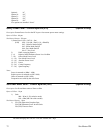
Set SPA Minimum Sweep Time - Control Byte #53 (35h)
Description: Sets the minimum sweep time (in ms) for the spectrum analyzer when the span is 0.
Valid range is 50 to 200,000,000.
Bytes to Follow: 4 bytes
1) Minimum Sweep Time (in ms) (highest byte)
2) Minimum Sweep Time (in ms)
3) Minimum Sweep Time (in ms)
4) Minimum Sweep Time (in ms) (lowest byte)
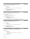
Site Master Returns: 1 byte
1) 255 (FFh) Operation Complete Byte
224 (E0h) Parameter Error: Invalid sweep time
238 (EEh) Time-out Error
Set Trigger Position - Control Byte #54 (36h)
Description: Sets the trigger position (in percent) for the spectrum analyzer when the span is 0.
Bytes to Follow: 1 byte
1) Trigger Position (0 - 100%)
Site Master Returns: 1 byte
1) 255 (FFh) Operation Complete Byte
224 (E0h) Parameter Error: Invalid trigger position
238 (EEh) Time-out Error
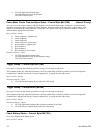
Set Video Trigger Level - Control Byte #55 (37h)
Description: Sets the trigger level (-120 - +20 dBm) for the spectrum analyzer when the span is 0 and trigger mode is video.
The trigger level should be sent as (value in dBm * 1000) + 120,000.
Bytes to Follow: 4 bytes
1) Trigger Level (highest byte)
2) Trigger Level
3) Trigger Level
4) Trigger Level (lowest byte)
Site Master Returns: 1 byte
1) 255 (FFh) Operation Complete Byte
Site Master PM 75


