


Rack LCD Console KVM Switch User’s Manual4
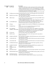
Item Number Component Description
EXIT button 1. Pressing the EXIT button without opening the On Screen Display (OSD)
initiates an auto adjustment which restores the display defaults of the OSD.
2. While the OSD user interface is in use, press the EXIT button to exit the
current menu and return to the previous menu or press the EXIT button to leave
an adjustment menu when the adjustment is complete.
3. From the Main Menu screen, pressing the EXIT button, will exit the OSD.
Left/Down Arrows button Pressing this button moves left or down through the menu and decreases the
value when making an adjustment.
Right/Up Arrows button Pressing this button moves right or up through the menu and increases the
value when making an adjustment.
MENU button 1. If the OSD user interface has not been opened, pressing the MENU button
initiates it and brings up the Main menu.
2. While the OSD user interface is in use, when a setting choice is reached,
pressing the MENU button brings up the setting’s adjustment screen.
LCD POWER button Turns on power to the LCD monitor. An LED light next to the switch will
illuminate when the monitor is in stand-by (power-saver) mode.
USB port Connect a peripheral device (flash drive, CD-ROM drive) to the KVM Rack
LCD.
UPGRADE port An RJ-11 port to be used to transfer firmware upgrades from the
administrator’s server to the KVM Rack LCD.
FW UPGRADE
NORMAL / RECOVERY
The Firmware Upgrade switch should be in the NORMAL position during
normal operation of the KVM Rack LCD. The switch is set to RECOVERY
only when a Firmware Upgrade Recovery is performed. (See “Firmware
Upgrade Recovery” on page 24 for more information.)
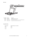
LCD monitor The LCD display monitor of the KVM Rack LCD.
RESET switch Press this recessed switch in with a small object (such as a pen point) to
perform a system reset.
SCROLL LOCK LED When illuminated, the SCROLL LOCK LED indicates the scroll lock function
on the keyboard is enabled.
CAPS LOCK LED When illuminated, the CAPS LOCK LED indicates the capitals lock function
on the keyboard is enabled.
NUM LOCK LED When illuminated, the NUM LOCK LED indicates the number lock function
on the keyboard is enabled.
STATION ID UP button Station ID selection button. Pressing the UP button repeatedly scrolls up
through the list of available stations.
STATION ID DOWN
button
Station ID selection button. Pressing the DOWN button repeatedly scrolls
down through the list of available stations.
STATION ID LED
display
Two digit LED display shows the Station ID.
PORT ID UP button Port ID selection button. Pressing the UP button repeatedly scrolls up through
the list of available ports.
PORT ID DOWN button Port ID selection button. Pressing the DOWN button repeatedly scrolls down
through the list of available ports.
PORT ID LED display Two digit LED display shows the Port ID.
ON LINE LED display When lit, indicates the computer attached to that port is up and running.