


5
3 Installation and Setup
3.1 Handling
Call-UPS II is sensitive to electrostatic discharge. It is shipped in a con-
ductive bag to help dissipate damaging static charges. Leave the product
in the bag until ready to install. Handle Call-
UPS II by the end plate only.
Do not touch the printed circuit board or other components.
3.2 Receiving Inspection
Once the Call-UPS II has been removed from its shipping container,
inspect it for damage that may have occurred while in transit. Notify
the carrier and place of purchase immediately if any damage is found.
The packing materials are recyclable and should be disposed of properly.
Please complete and return the enclosed warranty card.
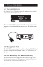
Call-
UPS II is shipped with a null modem cable (APC part number 940-
0103).
3.3 Installation
Before installing Call-UPS II, install your UPS. Then refer to the appro-
priate section that follows.
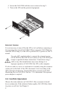
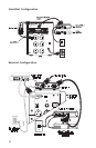
SmartSlot
If you are using a SmartSlot Call-UPS II with other SmartSlot devices,
refer to the appendix, “Multiple SmartSlot Installation” on pages 42–43.
While it is not possible to install the Call-
UPS II upside down, you can
damage the unit in the attempt to do so. Note the proper orientation of the
Call-
UPS II shown in the figure that follows. The sides of the printed cir-
cuit board align with the locating slots in the sides of the SmartSlot. In a
UPS, the SmartSlot may be oriented horizontally or vertically.
Use the following procedure to install the Call-
UPS II:
1 Shut down the protected loads and turn off the UPS.
2 Use a #2 Phillips head screwdriver to remove the two screws re-
taining the cover. Keep the screws handy for step 4 below. Retain
the cover for future use.
3 Orient the Call-
UPS II to fit in the SmartSlot as shown below.
Slide the Call-
UPS II all the way into the SmartSlot. The panel of
the Call-
UPS II should be flush with the front face of the slot.