


- 10 -
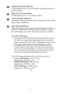
DC Trigger jacks
When connected to a component acting as a DC trigger, that
component controls turn on/off of the ‘delayed’ outlet banks.
The H10 also allows that DC signal to pass through to another
connected component.
CAUTION: When connecting to the DC Trigger jacks, con-
nect the source of the DC trigger to the IN jack. The OUT jack
should be used only as a pass-through. The DC Trigger signal
can be short circuited if the input and output cables are
reversed. The maximum input voltage for the DC Trigger is
30VDC. Do not apply an AC voltage to the DC trigger jacks.
Failure to comply with this statement may result in equipment
damage.
Surge Protected Telephone Jacks
The H10 provides a telephone line splitter with surge protection
to protect components connected via telephone line. Connect
the supplied RJ11 Telephone cable from the wall jack (source)
to the telephone line connector marked “IN”. Connect other
telephone cables to the connectors marked “OUT A” and/or
“OUT B” and then to the equipment to be protected (Telephone,
DVR, DSS, or DSL).
Additional Surge Protected COAX/RF Connectors
The H10 also provides a surge protection for your DSS system
or RF Antenna system. The surge protection feature prevents
surges traveling over Coaxial cable from damaging the equip-
ment.
Connect the coaxial cable from the DSS or Antenna system to
the connector marked “IN.”
Connect another coaxial cable from the connector marked
“OUT” to the device being protected (DSS or Antenna).
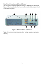
6
7
8