


Campus Wireless Networks Validated Reference Design Version 3.3 | Design Guide Campus WLAN Validated Reference Design | 19
Chapter 4
Campus WLAN Validated
Reference Design
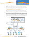
This chapter presents a more complex network model representing a common Aruba deployment in a
large campus WLAN environment.
Enterprise networks support thousands of employees, with rigorous service level expectations. To
meet these requirements, a reference wired network architecture that defines Core, Distribution and
Access elements has become well established among IT network professionals. These elements form
the building blocks of large scale, highly-available networks. Vendor validation of their products against
this conceptual reference architecture provides IT organizations with assurance that products will
perform and interoperate as expected.
Aruba User-Centric Enterprise Wireless Networks also support large numbers of users with stringent
service level expectations. To enable IT network architects to successfully plan deployments, Aruba
has developed a Validated Reference Design (VRD) that leverages the experience of more than 3,500
customer deployments, peer-review by Aruba engineers, and extensive performance testing. This
reference design leverages and extends the familiar wired model in order to deploy a user-centric
network as an overlay.
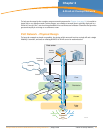
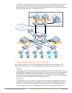
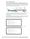
Aruba Campus WLAN Physical Architecture
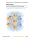
The Validated Reference Design network model described in this chapter is referenced throughout the
remainder of this book. The model depicts a cluster-based architecture typical of large enterprise
deployments. For this type of deployment it is a best practice to employ distributed control and data
planes using a hierarchical ‘Master/Local’ strategy with separate controller clusters providing each
service. This will provide a scalable highly available architecture for data and voice traffic throughout
the enterprise.
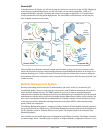
Some key components of this reference model include:
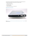
z Master Controllers – Two MMC-3600 model appliances configured to use Master redundancy. Each
controller has redundant gigabit Ethernet links into the data center distribution switches, and share
a Virtual Router Redundancy Protocol (VRRP) address.
z Local Controllers – Aruba Local Controllers consist of Multiservice Mobility Module blades in an
MMC-6000 chassis. In the Aruba VRD, these Mobility Controllers are running in “active-active”
redundancy, with two VRRP addresses shared between them. Each controller has two 10 gigabit
Ethernet links bonded via Etherchannel to a single distribution layer switch.
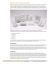
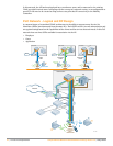
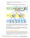
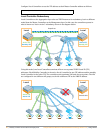
z Access Points – Dual radio (A/B/G) AP65 access points are deployed throughout the enterprise
carpeted space, providing high bandwidth access across the 2.4 GHz and 5Ghz bands. These APs are
densely deployed. “Dense Deployment” uses a microcell architecture to cover an area using
overlapping APs at relatively low transmit power. This design strategy enables ARM to detect and
close coverage holes in the event of an AP failure by increasing power on neighboring APs. Smaller
cells also help ensure proper load balancing of Voice over WLAN callers.
z SSIDs – There are three Service Set Identifiers present in the Reference Design. One SSID is used for
employees and runs WPA2 for authentication and encryption. A second SSID is used by applications
such as voice or video, and runs WPA with a Pre-Shared Key for authentication and encryption. The
final SSID is open with a web based captive portal for authentication and is used by guests. Each
user or device that associates with the network is placed in a role that is enforced by the stateful
firewall.