


Campus Wireless Networks Validated Reference Design Version 3.3 | Design Guide Alternative Deployment Architectures | 71
Appendix C
Alternative Deployment
Architectures
This Campus Wireless LAN Reference Architecture represents a large scale, highly available WLAN
deployment model in a single large campus environment. While this is the recommended deployment
for this environment, there are other reference architectures that are considered best practices at
different scales, and for different types of customers. Aruba has identified four specific reference
architecture models in addition to the Campus WLAN that are commonly deployed by our customers.
z Small Deployment (No Redundancy)
z Medium Deployment (1:1 Redundancy)
z Branch Office (N+1 Redundancy)
z Pure Remote Access (1:1 Redundancy)
Each of these scenarios will be covered briefly in the following sections. All of these architectures
include a concept of an Aggregation layer and a Management layer as well as discussion of available
redundancy options and controller placement. The recommendations for VLANs, profiles, and AP
placements are the same as for the Campus WLAN for the most part.
Small Network Deployment
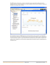
In a small office the network will look much like the Proof-of-Concept design in Chapter 3 on page 15,
with a single Mobility Controller and a limited number of APs and AMs. This type of WLAN deployment
is typically specified where the WLAN is a convenience network that is not relied upon as the primary
connection by users and voice services are not present.
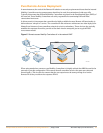
In this scenario the Management layer and Aggregation layer are contained within the same controller,
and there is no redundancy. Should the Mobility Controller become unreachable, all APs will go down
and the wireless network will be unavailable until the Mobility Controller is once again online.
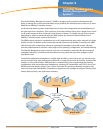
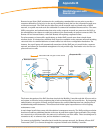
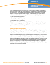
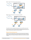
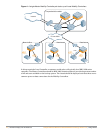
In this scenario, the Mobility Controller is typically deployed in either the network data center or in the
wiring closet. The choice is typically dependent on the physical size of the network and Power-over-
Ethernet (PoE) requirements. In a larger physical network that is deploying WLAN in hotspots, the
Mobility Controller should be located in the data center. In very small networks where PoE from the
controller will also power the APs, the Mobility Controller should be located in the wiring closet. Both
options are shown in the following diagrams.