


User’s Manual 13
Chapter 2. Hardware Installation
This chapter describes the panel layout
and installation procedure of the
FriendlyNET Cable/DSL Router.
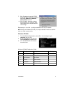
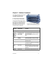
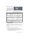
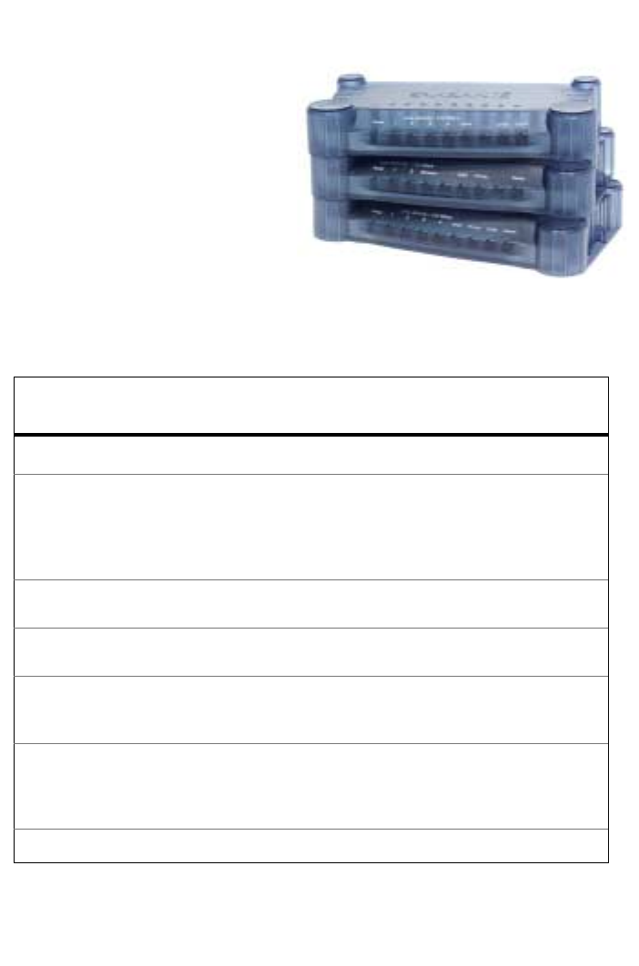
2.1 Front Panel Information
The front panel features status indica-
tor LEDs for four 10/100 Mbps Ethernet
ports (or two 10/100 ports on the wire-
less models only), one wide area net-
work (WAN) port plus the Printer and
COM (serial) ports, if applicable.
LED Label LED Description LED Status
Power
Power On when the router has power
1, 2, 3, 4
(1 and 2 only
for the
FR3002AL
model)
Two indicators per port
Left: Link-Activity
Right: 100 Mbps
Left: On with valid network connection; blinks when
there is network activity
Right: On for 100 Mbps (Fast Ethernet), off for 10
Mbps
WAN
Cable/DSL
Link-Activity
On with valid Cable/DSL connection; blinks when
there is network activity. This port runs at 10 Mbps
Printer
Printer Activity FR3004LC and FR3002AL models only: On when
print server is active
COM
Com Activity FR3004C/FR3004LC only: On when dial-up modem
is connected (to the COM port) and is active (WAN
type is Dial-up or ISDN)
Status
System Status Blinks when the unit is first powered on (Power On
Self Test); LED remains OFF in firmware versions
2.5 or later. In earlier firmware versions, the LED
remains ON.
Wireless
Wireless Status Blinks rapidly when wireless transmission occurs.
This front panel applies to FR3002AL, FR3004C and
FR3004LC routers manufactured after August 2000.