


26 ASUS A7V266 User’s Manual
3. HARDWARE SETUP
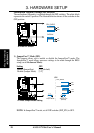
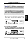
System Memory
3. H/W SETUP
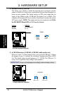
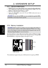
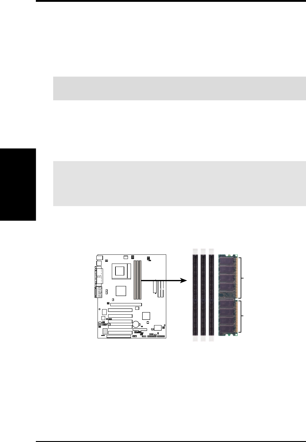
A7V266 184-Pin DDR
DIMM Sockets
80 Pins
104 Pins
A7V266
01010 1
3.5.1 General DIMM Notes
• DIMMs that have more than 18 chips are not supported on this motherboard.
• ASUS motherboards support SPD (Serial Presence Detect) DIMMs. This is the
memory of choice for best performance vs. stability.
• BIOS shows SDRAM memory on bootup screen.
• Single-sided DDR DIMMs come in 64, 128, and 256MB; double-sided come in
128, 256, and 512MB.
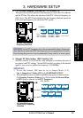
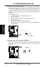
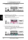
3.5.2 Memory Installation
WARNING! Make sure that you unplug your power supply when adding or
removing memory modules or other system components. Failure to do so may
cause severe damage to both your motherboard and expansion cards (see 3.3
Hardware Setup Procedure for more information).
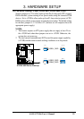
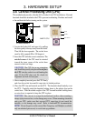
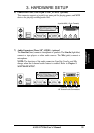
Insert the module(s) as shown. Because the number of pins are different on either
side of the breaks, the module will only fit in the orientation shown. A 184-pin DDR
DRAM DIMM has a single notch slightly to the right of center.
This motherboard supports three pairs of differential clock signals per DIMM.
WARNING! Be sure that the DIMMs you use can handle the specified DDR
RAM MHz or else bootup will not be possible.