


ASUS A7V266 User’s Manual 41
3. HARDWARE SETUP
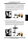
Connectors
3. H/W SETUP
A7V266
01010 1
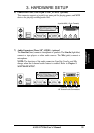
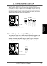
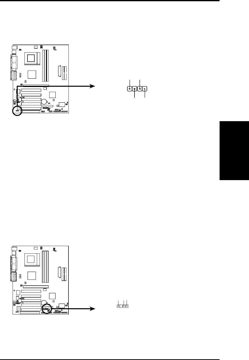
A7V266 Digital Audio Interface
SPDIFINSPDIFOUT
GND
GND
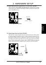
21) Digital Audio Interfaces (2-pin SPDIFOUT/CDSPDIFIN) (optional)
These connectors connect SPDIF audio cable that allows digital instead of analog
sound output from CD-ROM, DVD-ROM, CD-RW, and advanced sound cards
such as SoundBlaster. Live.
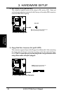
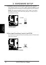
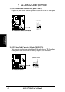
22) Chassis Open Alarm Lead (4-pin CHASSIS)
This lead is for a chassis designed for chassis intrusion detection. This requires
an external detection mechanism such as a chassis intrusion monitor/sensor or
microswitch. When any chassis component is removed, the sensor is triggered
and a high-level signal is sent to this lead to record a chassis intrusion event.The
event is then be processed by software such as LDCM. When not using the
chassis intrusion lead, place a jumper cap over the pins to close the circuit.
A7V266 Chassis Open Alarm Lead
CHASSIS
+5Volt
(Power Supply Stand By)
Ground
Chassis Signal
1
A7V266
01010 1