


ASUS A7V266-EX User’s Manual 23
3. HARDWARE SETUP
3. H/W SETUP
Motherboard Settings
R
A7V266-EX
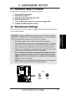
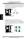
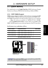
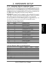
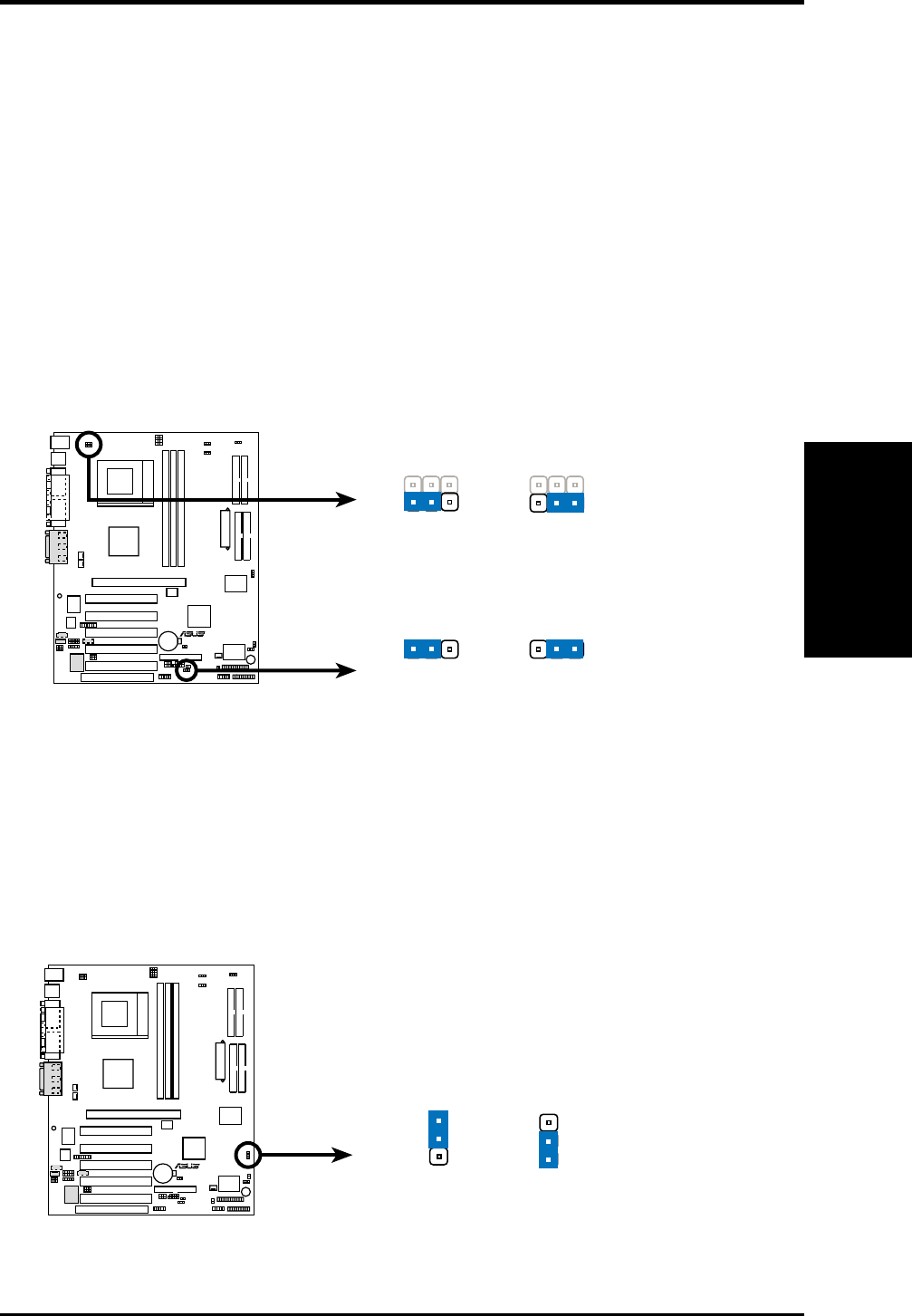
A7V266-EX USB Device Wake Up
USB23_PWR
USB01_PWR
+5VSB
23
+5V
12
+5V
1
2
+5VSB
2
3
(Default)
(Default)
8) USB Device Wake-up (USB01_PWR/USB23_PWR/USB45_PWR)
Set these jumpers to +5V to allow wake up from the S1 sleep state (CPU stopped;
RAM refreshed; system running in low power mode) using the connected USB
devices. Set to +5VSB to allow wake up from S3 sleep state (no power to CPU;
RAM in slow refresh; power supply in reduced power mode). The default setting
for the three jumpers is 1-2 to select +5V (because not all computers have the
appropriate power supply).
NOTES:
1. This feature requires an ATX power supply that can supply at least 2A on
the +5VSB lead when these jumpers are set to +5VSB. Otherwise, the
system does not power up.
2. The total current consumed must NOT exceed the power supply capability
(+5VSB) whether under normal working conditions or in sleep mode.
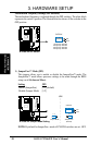
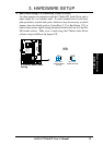
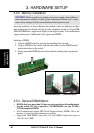
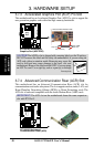
9) Promise RAID Controller (RAID_EN) (Optional)
These jumpers enable the Promise RAID controller functions. The default setting,
[1-2] enables the Promise RAID controller for RAID0/1. Resetting the jumper
caps to [2-3] overrides the Promise controller. The IDE controller always
functions at ATA-133 for hard disk drives whether or not the RAID controller is
activated or not.
R
A7V266-EX
A7V266-EX ATA133/RAIDO Selection
DisableEnable
(Default)
1
2
3
2
RAID_EN