


ASUS A7V266-EX User’s Manual 37
3. HARDWARE SETUP
Connectors
3. H/W SETUP
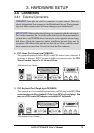
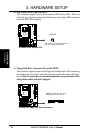
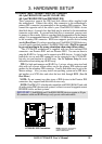
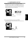
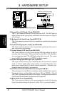
13) Infrared Module Connector (10-1 pin IR_CON)
This connector supports an optional wireless transmitting and receiving infrared
module. This module mounts to a small opening on system cases that support
this feature. You must also configure the setting through UART2 Use Infrared
(see 4.4.2 I/O Device Configuration) to select whether UART2 is directed for
use with COM2 or IrDA. Use the five pins as shown in Back View and connect
a ribbon cable from the module to the motherboard SIR connector according to
the pin definitions. (NOTE: The SIR module is not supplied with the
motherboard. The CIR module is currently not available.)
R
A7V266-EX
A7V266-EX Infrared
Module Connector
Standard Infrared (SIR)
Front View Back View
+5V
IRTX
IRRX
(NC)
GND
SIR
+5V
IRRX
IRTX
(NC)
GND
IRAX
GND
CIRRX
CIR+5V
CIR
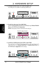
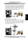
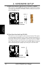
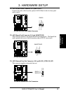
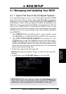
14) ASUS iPanel Connector (24-1 pin AFPANEL)
This connector supports an optional ASUS iPanel, an easy to access drive bay
with front I/O ports, status LEDs, and space reserved for a hard disk drive.
Alternatively, if not using an ASUS iPanel, connect an optional wireless
transmitting and receiving infrared module to the SIR connector, or an optional
consumer infrared connector set for wireless transmitting/remote control functions
through one external infrared module.
R
A7V266-EX
A7V266-EX Front Panel Connectors
+5VSB
NC
CHASSIS#
+5 V
PCIRST#
GND
NC
EXTSMI#
MLED-
NC
BATT
NC
SMBDATA
GND
+3VSB
IRRX
IRTX
NC
NC
NC
+5V SMBCLK
AFPANEL
Standard Infrared (SIR)
Front View Back View
+5V
IRTX
IRRX
(NC)
GND
+5VSB
NC
+5 V
GND
NC
NC
GND
IRRX
IRTX
CIR
SIR
IR_CON