


Chapter 2: Hardware setup
2-34
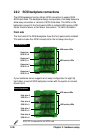
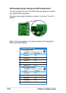
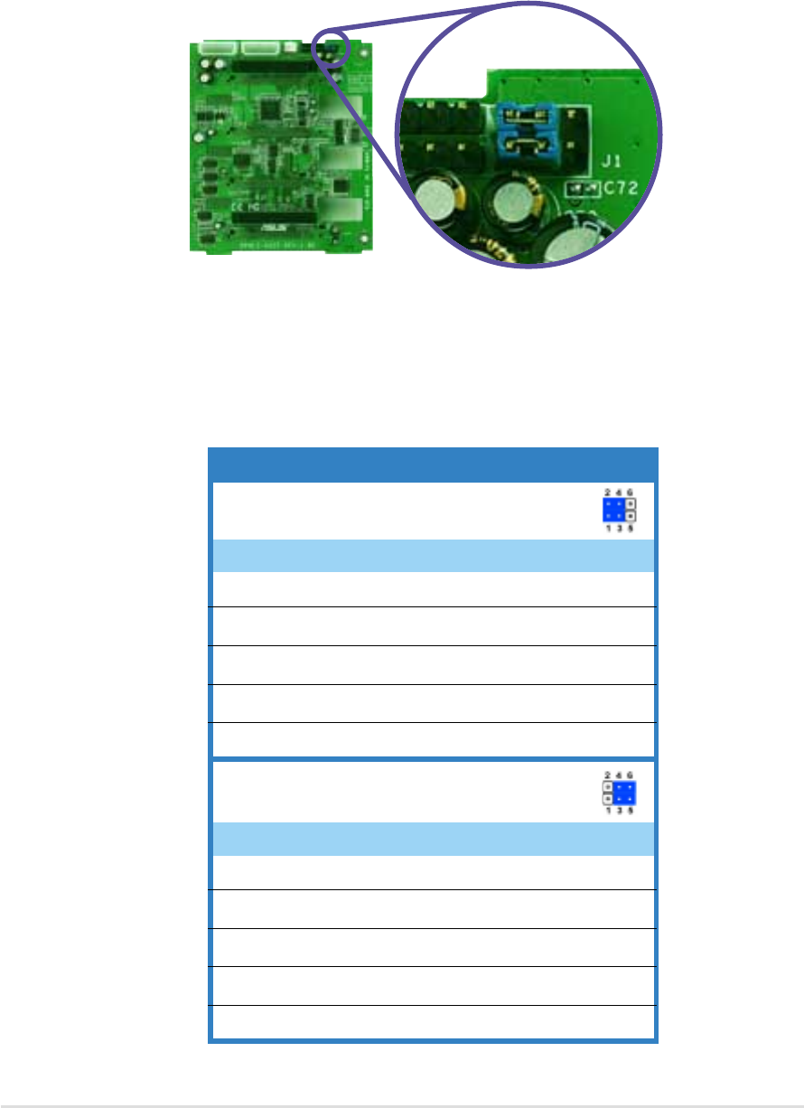
SCSI backplane jumper settings and HDD ID assignments
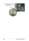
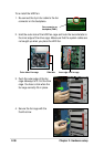
The 6-pin jumper J1 on each of the SCSI backplanes allows you to define
your desired SCSI configuration.
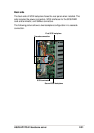
The picture below shows the location of jumper J1 with pins 1-3 and 2-4
shorted.
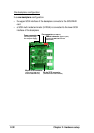
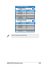
Cascade configuration
First backplane (BPB1)
J1 setting
(1-3 shorted, 2-4 shorted)
Device SCSI ID#
Drive Bay 1 ID0
Drive Bay 2 ID1
Drive Bay 3 ID2
Drive Bay 4 ID3
GEM SAF-TE ID15
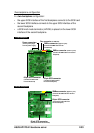
Second backplane (BPB2)
J1 setting
(3-5 shorted, 4-6 shorted)
Device SCSI ID#
Drive Bay 5 ID4
Drive Bay 6 ID5
Drive Bay 7 ID6
Drive Bay 8 ID8
GEM SAF-TE ID11
Refer to the following tables for the jumper settings and the appropriate
ID# for each SCSI HDD bay.