


14
ASUS TUEG-VM User’s Manual
3. HARDWARE SETUP
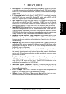
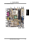
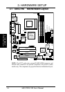
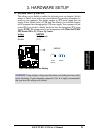
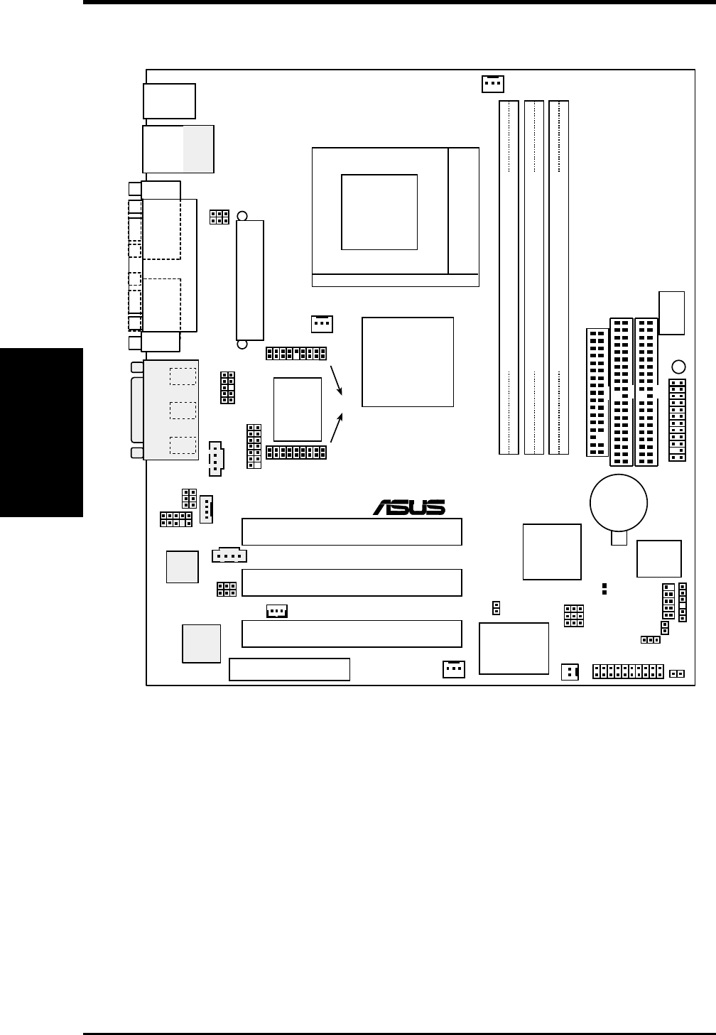
3.1 TUEG-VM Motherboard Layout
Motherboard Layout
3. H/W SETUP
NOTE: The AC’97 audio codec, external GAME/AUDIO connectors, and
internal audio connectors are optional components, and present in audio
models only. The components are grayed in the above motherboard layout.
ACHA
PWR_FAN
PANEL
IDELED
FLOPPY
SECONDARY IDE
PRIMARY IDE
TUEG-VM
CHA_FAN
CD
AUX
®
LED
CR2032 3V
Lithium Cell
CMOS Power
R210
DSW
Socket 370
CNR_SLOT
ATX Power Connector
CPU_FAN
MODEM
WOL_CON
WOR
CNRUSB2
CNRUSB1
AAPANEL
MIC2
HEADPHONE
JEN
COM2
AFPANEL
DIP
Switches
ASUS ASIC
with
Hardware
Monitor
LCDTV
Intel I/O
Controller
Hub
(ICH2)
Intel 815G
Graphics &
Memory
Controller
Hub (GMCH)
SMB
2Mbit
Firmware
Hub
(FWH)
USB2
LAN_EN
USBPWR2
SMARTCARD
USBPWR1
KBPWR
Super
I/O
3Com
3C920
Fast
Ethernet
DIMM1 (64/72 bit, 168-pin module)
1
0
DIMM2 (64/72 bit, 168-pin module)
3
2
DIMM3 (64/72 bit, 168-pin module)
5
4
PCI3
PCI2
PCI1
11
1
COM1
PARALLEL PORT
VGA
GAME_AUDIO
Mic
In
Line
Out
Line
In
PS/2KBMS
T: Mouse
B: Keyboard
AUD_EN
Audio
Codec
JTPWR
USB
T: USB1
B: USB2
Top:
RJ-45