


40 ASUS TUEG-VM User’s Manual
Connectors
3. H/W SETUP
3. HARDWARE SETUP
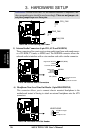
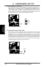
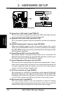
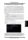
14) LCD-TV Headers (18-pin, 18-1 pin LCDTV)
These headers require an optional LCD module for LCD output or a TV-out
module for TV output.
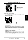
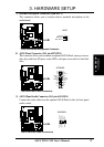
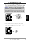
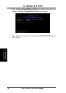
15) USB Headers (10-1 pin USB2)
If the USB Ports on the back panels are inadequate, a USB header is available
for two additional USB ports. Connect the 10-1 pin ribbon cable from the provided
2-port USB connector set to the midboard 10-1 pin USB header and mount the
USB connector set to an open slot on your chassis.
NOTE: To use this header, make sure that the USBCNR1/USBCNR2 jumpers
(see 3.4 Motherboard Settings) are set to USB Connect.
TUEG-VM
®
TUEG-VM USB Headers
USB2
1
5
6
10
1: USB Power
2: USBP2–
3: USBP2+
4: GND
5: NC
6: USB Power
7: USBP3–
8: USBP3+
9: GND
TUEG-VM
®
TUEG-VM LCD-TV Headers
LCDTV
LTVCL
+3V
ROMSEN
TVVSYNC
GND
DD4
DD3
DD1
GND
+1.8V
LTVDA
GND
BLANK
TVHSYNC
GND
DD2
DD0
1
+5V
GND
DD11
DD9
DD7
GND
DD5
CLKOUT1
+5V
PCIRST#
DD10
GND
DD8
DD6
CLKOUT0
GND