


ASUS TUEG-VM User’s Manual 35
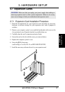
3. HARDWARE SETUP
Connectors
3. H/W SETUP
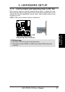
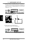
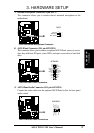
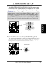
3) IDE Activity LED (2-pin IDELED)
This connector supplies power to the cabinet’s IDE activity LED. Read and
write activity by devices connected to the Primary or Secondary IDE connectors
will cause the LED to light up.
TUEG-VM
®
TUEG-VM IDE Activity LED
TIP: If the case-mounted LED does not
light, try reversing the 2-pin plug.
IDELED
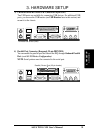
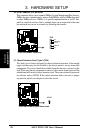
4) Power Supply (PWR_FAN), CPU (CPU_FAN), Chassis (CHA_FAN) Fan
Connectors (3 pins)
These connectors support cooling fans of 350mA (4.2 Watts) or less. Orientate
the fans so that the heat sink fins allow airflow to go across the onboard heat
sink(s) instead of the expansion slots. Depending on the fan manufacturer, the
wiring and plug may be different. The red wire should be positive, while the
black should be ground. Connect the fan’s plug to the board taking into
consideration the polarity of the connector.
NOTE: The “Rotation” signal is to be used only by a specially designed fan with
rotation signal. The Rotations per Minute (RPM) can be read directly from the
ASUS iPanel or monitored using a utility such as ASUS PC Probe or Intel LDCM.
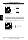
TUEG-VM
®
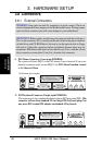
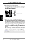
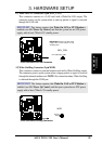
TUEG-VM IDE Connectors
NOTE: Orient the red markings
(usually zigzag) on the IDE
ribbon cable to PIN 1.
Secondary IDE Connector
PIN 1
Primary IDE Connector