


15
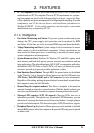
3. HARDWARE SETUP
ASUS TUEG-VM User’s Manual
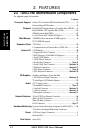
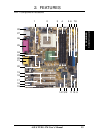
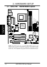
3.2 Layout Contents
Motherboard Settings
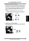
1) JEN p. 18 JumperFree™ Mode (Enable/Disable)
2) USBPWR1 p. 19 USB Device Wake Up (Enable/Disable)
USBPWR2
3) USBCNR1/USBCNR2 p. 19 USB/CNR Selection (USB2 Connect/CNR)
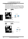
4) AUD_EN1 p. 20 Onboard Audio CODEC Setting (Enable/Disable)
5) LAN_EN p. 20 Onboard LAN Setting (Enable/Disable)
6) KBPWR p. 21 Keyboard Power Up (Enable/Disable)
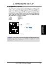
7) DSW p. 22 CPU External Frequency Setting
Expansion Slots
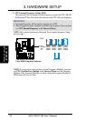
1) DIMM 1/2/3 p. 24 168-Pin System Memory Support
2) CPU p. 26 Central Processing Unit (CPU)6
3) PCI1/2/3 p. 27 32-bit PCI Bus Expansion Slots
4) CNR1 p. 28 Communication and Network Riser Slot
External Connectors
1) PS2KBMS p. 30 PS/2 Mouse Connector (6-pin female)
2) PS2KBMS p. 30 PS/2 Keyboard Connector (6-pin female)
3) USB p. 31 Universal Serial Bus Ports (Two 4-pin female)
4) PRINTER p. 31 Parallel Port Connector (25-pin female)
5) COM1/COM2 p. 32 Serial Port Connectors (9-pin male, 10-1 pin)
6) VGA p. 32 Monitor Output Connector (15-pin female)
7) GAME_AUDIO p. 33 Game/MIDI Connector (15-pin female) (optional)
8) LINE-IN, -OUT, MIC p. 33 Audio Port Connectors (Three 1/8” female) (optional)
9) RJ-45 p. 33 Fast Ethernet Port Connector (optional)
Internal Connectors
1) FLOPPY p. 34 Floppy Disk Drive Connector (34-1pins)
2) PRIMARY/SECONDARY IDE p. 35 Primary/Secondary IDE Connectors (Two 40-1pins)
3) IDELED p. 35 IDE Activity LED (2 pins)
4) CPU_FAN, PWR_FAN p. 35 CPU, Power Supply, Chassis Fan Connectors (Three 3-pin)
CHA_FAN
5) CD1, AUX, MODEM p. 36 InternalAudio Connectors (optional)
6) HEADPHONE p. 36 Headphone True-Level Line Out Header (3 pins)
7) MIC2 p. 37 Internal Microphone Connector (3 pins)
8) AFPANEL p. 37 ASUS iPanel Connector (24-1 pins)
9) AAPANEL p. 37 ASUS iPanel Audio Connector (10-1 pins)
10) SMB p. 38 SMBus Connector (6-1 pins)
11) ACHA p. 38 Chassis Intrusion Connector (2 pins)
12) WOL_CON p. 39 Wake-On-LAN Connector (3 pins)
Layout Contents
3. H/W SETUP