


20 ASUS CUVL-VM User’s Manual
3. HARDWARE SETUP
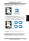
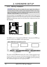
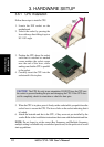
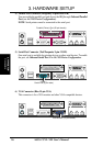
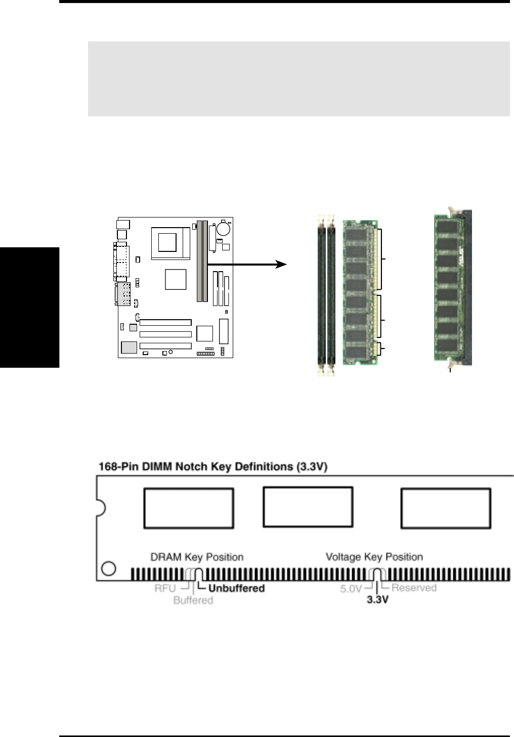
Insert the module(s) into the DIMM sockets as shown. Because the number of pins
are different on either side of the breaks, the module only fits in one direction. SDRAM
DIMMs have different pin contacts on each side and have a higher pin density than
DRAM SIMMs.
The notches on the DIMM shifts between left, center, or right to identify the type
and also to prevent the wrong type from being inserted into the DIMM slot on the
motherboard. You must tell your retailer the correct DIMM type before purchasing.
This motherboard supports four clock signals per DIMM.
The DIMMs must be 3.3Volt unbuffered SDRAMs. To determine the DIMM type,
check the notches on the DIMMs (see the figure below).
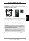
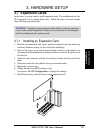
WARNING! Make sure that you unplug the power supply when adding or
removing memory modules or other system components. Failure to do so may
cause severe damage to both the motherboard and expansion cards (see 3.3
Hardware Setup Procedure for more information).
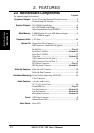
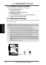
System Memory
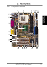
3. H/W SETUP
3.5.2 Memory Installation
CUVL-VM 168-Pin DIMM Sockets
Lock
20 Pins
60 Pins
88 Pins
CUVL-VM