


28 ASUS CUVL-VM User’s Manual
3. HARDWARE SETUP
Connectors
3. H/W SETUP
3.8.2 Internal Connectors
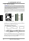
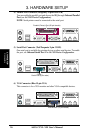
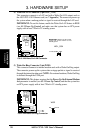
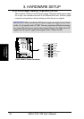
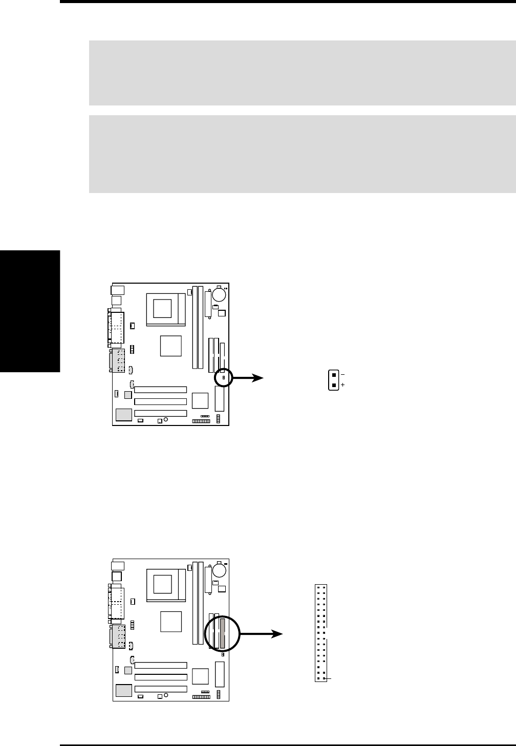
2) Floppy Disk Drive Connector (34-1 pin FLOPPY)
This connector supports the provided floppy drive ribbon cable. After connecting
the single end to the board, connect the two plugs on the other end to the floppy
drives. (Pin 5 is removed to prevent inserting in the wrong orientation when
using ribbon cables with pin 5 plugged).
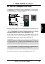
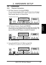
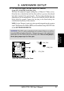
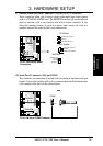
1) IDE Activity LED (2-pin IDELED)
This connector supplies power to the cabinet’s IDE activity LED. Read and
write activity by devices connected to the Primary or Secondary IDE connectors
cause the IDE LED to light up.
IDELED
CUVL-VM IDE Activity LED
CUVL-VM
TIP: If the case-mounted LED does not
light, try reversing the 2-pin plug.
NOTE: Orient the red markings on
the floppy ribbon cable to
PIN 1
CUVL-VM Floppy Disk Drive Connector
PIN 1
CUVL-VM
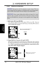
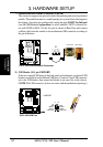
WARNING! Some pins are used for connectors or power sources. These are
clearly distinguished from jumpers in the Motherboard Layout. Placing jumper
caps over these connector pins will cause damage to your motherboard.
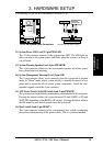
IMPORTANT: Always connect ribbon cables with the red stripe to Pin 1 on the
connectors. Pin 1 is usually on the side closest to the power connector on hard
drives and CD-ROM drives, but may be on the opposite side on floppy disk
drives.