


2-42
Chapter 2: Hardware information
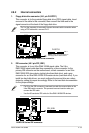
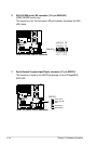
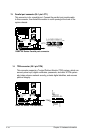
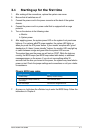
13. Parallel port connector (26-1 pin LPT1)
This connector is for a parallel port. Connect the parallel port module cable
to this connector, then install the module to a slot opening at the back of the
system chassis.
®
DSBF-DE Series Parallel port connector
LPT1
SPD7GND
SPD6GND
SPD5GND
SPD4GND
SLCT
PEGND
BUSY
ACK#GND
SPD3GND
SPD2SLIN#
SPD1PINIT#
SPD0ERROR#
STB#AFD#
GND
PIN 1
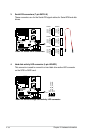
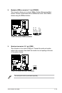
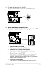
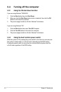
14. TPM connector (20-1 pin TPM)
This connector supports a Trusted Platform Module (TPM) system, which can
securely store keys, digital certicates, passwords, and data. A TPM system
also helps enhance network security, protects digital identities, and ensures
platform integrity.
®
DSBF-DE Series TPM connector
TPM1
CK_33M_TPM
LFRAMEn
LRESETn
LAD3
+3.3V
LAD0
+3.3V
X
GND
X
X
GPIO2
GPIO
LAD2
LAD1
GND
X
SERIRQ
X
X
PIN1