


ASUS DSBF-DE Series
2-43
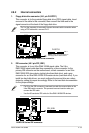
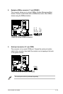
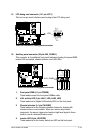
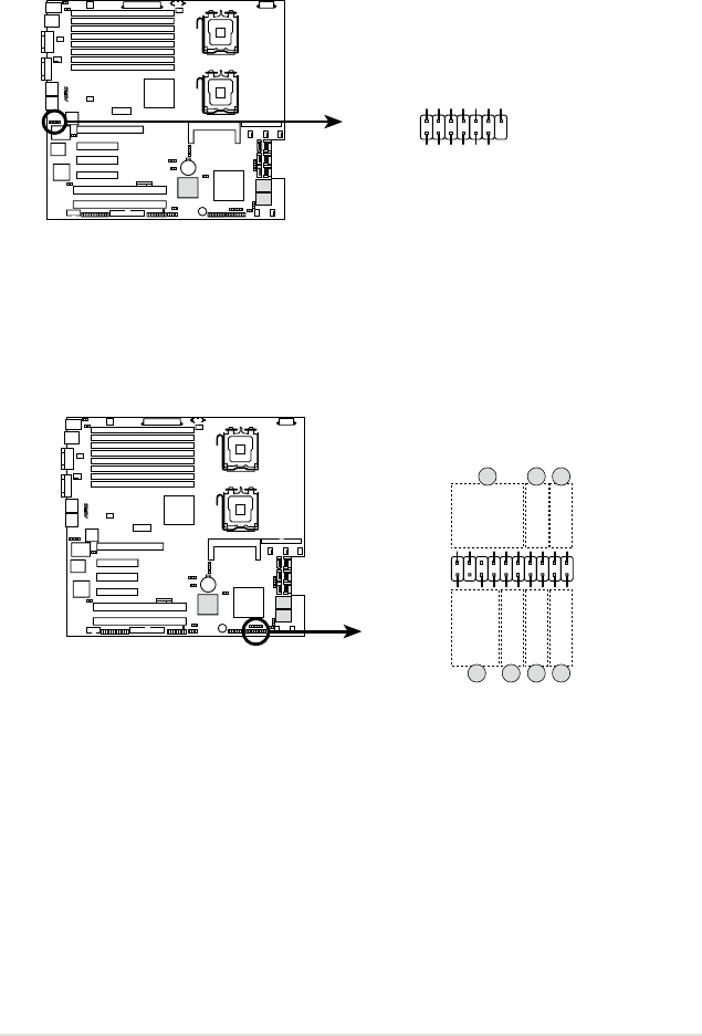
15. LPC debug card connector (14-1 pin LPC1)
This is a low pin count interface used to plug in the LPC debug card.
®
DSBF-DE Series LPC debug card connector
LPC1
+3.3V
PIN1
+3.3V+3.3V
GNDGND
LPC_LAD2LPC_LAD3
LPC_LAD0LPC_LAD1
PLTRSTLFRAME_N
CLKGND
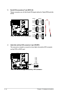
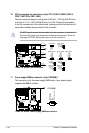
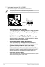
16. Auxiliary panel connector (20-pin AUX_PANEL1)
This connector is for additional front panel features including front panel SMB,
locator LED and switch, chassis intrusion, and LAN LEDs.
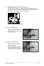
1.
Front panel SMB (6-1 pin FPSMB)
These leads connect the front panel SMBus cable.
2.
LAN activity LED (2-pin LAN1_LED, LAN2_LED)
These leads are for Gigabit LAN activity LEDs on the front panel.
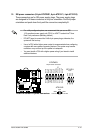
3
Chassis intrusion (4-1 pin CHASSIS)
These leads are for the intrusion detection feature for chassis with
intrusion sensor or microswitch. When you remove any chassis
component, the sensor triggers and sends a high-level signal to these
leads to record a chassis intrusion event.
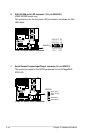
4.
Locator LED (6-pin LOCATOR)
These leads are for the locator switch and LED on the front panel.
®
DSBF-DE Series Auxiliary panel connector
AUX_PANEL1
I2C_4_DATA#LOCATORLED1+
+5VSBLOCATORLED1-
LAN1_LINKLOCATORBTN#
LAN1_ACTGND
+5VSB
I2C_4_CLK#
GNDGND
LAN2_ACTLOCATORLED2-
LAN2_LINKLOCATORLED2+
CASEOPEN
PIN1
NC
1 2 2
5 43 4