


36
3. HARDWARE SETUP
ASUS TR-DLS User’s Manual
3. H/W SETUP
Connectors
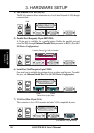
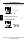
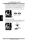
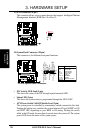
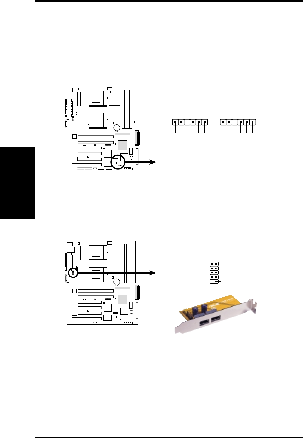
9) SMBus Connector (6-1 pin SMB, BPSMB)
These connectors allow you to connect SMBus (System Management Bus)
devices. SMBus devices communicate by means of the SMBus with an SMBus
host and/or other SMBus devices. SMBus is a specific implementation of an I
2
C
bus, which is a multi-device bus; that is, multiple chips can be connected to the
same bus and each one can act as a master by initiating data transfer.
The BPSMB connector is for a backplane board that supports an SMBus interface.
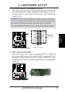
TR-DLS
TR-DLS USB Header
USBPORT
USB Power
USBP2–
USBP2+
GND
NC
USB Power
USBP3–
USBP3+
GND
1
5
6
10
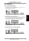
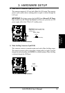
10) USB Header (10-1 pin USBPORT)
If the USB ports at the back panel are inadequate, one USB header is available
for two additional USB port connectors. Connect the USB header to a 2-port
USB connector set and mount the bracket to an open slot in the chassis.
TR-DLS
TR-DLS SMBus Connectors
SMB
1
SMBCLK
Ground
SMBDATA
+5V
FLOATING
BPSMB
1
SMBCLK
Ground
SMBDATA
+5V
FLOATING