


1-16
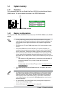
Chapter 1: Product introduction
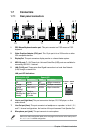
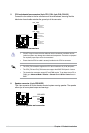
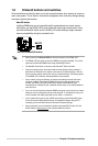
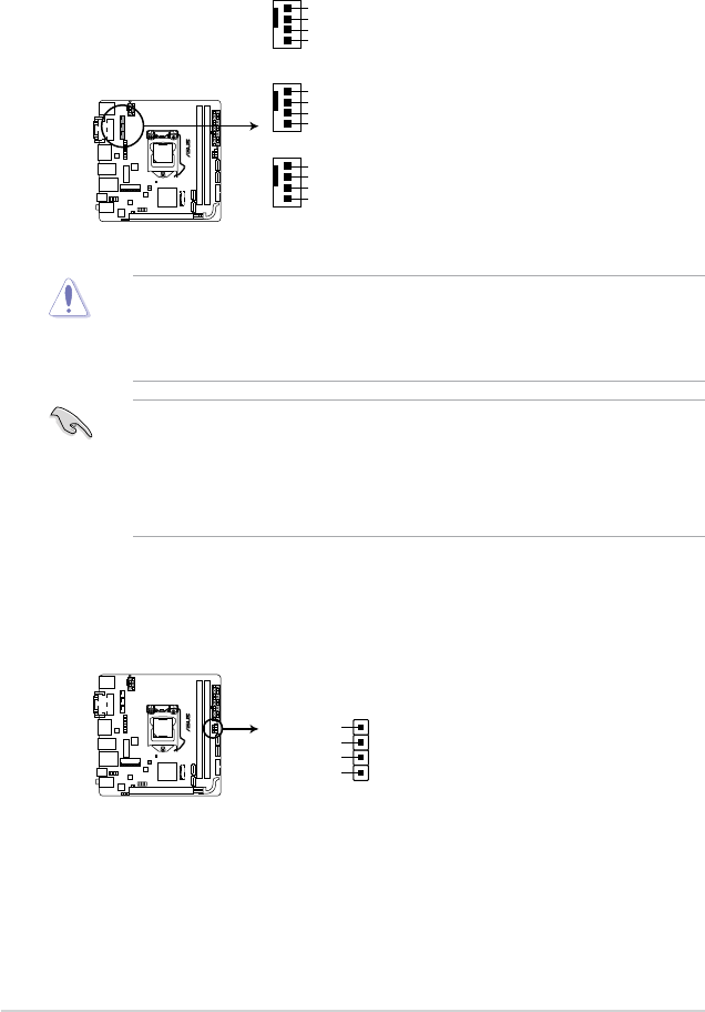
5. CPU and chassis fan connectors (4-pin CPU_FAN; 4-pin CHA_FAN1/2)
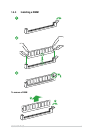
Connectthefancablestothefanconnectorsonthemotherboard,ensuringthatthe
black wire of each cable matches the ground pin of the connector.
• DONOTforgettoconnectthefancablestothefanconnectors.Insufcientairow
insidethesystemmaydamagethemotherboardcomponents.Thesearenotjumpers!
Donotplacejumpercapsonthefanconnectors!
• EnsurethattheCPUfancableissecurelyinstalledtotheCPUfanconnector.
• TheCPU_FANconnectorsupportstheCPUfanofmaximum1A(12W)fanpower.
• TheCPU_FANandCHA_FANconnectorssupporttheASUSFANXpert2+feature.
• ThechassisfanconnectorssupportDCandPWMmodes.TosetthesefanstoDCor
PWM,gotoAdvanced Mode > Monitor > Chassis Fan 1/2 Q-Fan Control items in
BIOS.
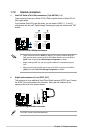
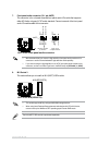
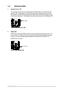
6. Speaker connector (4- pin SPEAKER)
This 4-pin connector is for the chassis-mounted system warning speaker. The speaker
allows you to hear system beeps and warnings.
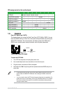
H97I-PLUS
H97I-PLUS Fan connectors
CHA_FAN2
GND
CHA FAN PWR
CHA FAN IN
CHA FAN PWM
CHA_FAN1
GND
CHA FAN PWR
CHA FAN IN
CHA FAN PWM
CPU_FAN
GND
CPU FAN PWR
CPU FAN IN
CPU FAN PWM
H97I-PLUS
H97I-PLUS Speaker out connector
Speaker Out
GND
GND
+5V
SPEAKER
PIN 1