


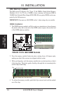
26 ASUS P2B-D2 User’s Manual
III. INSTALLATION
Connectors
III. INSTALLATION
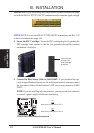
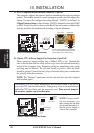
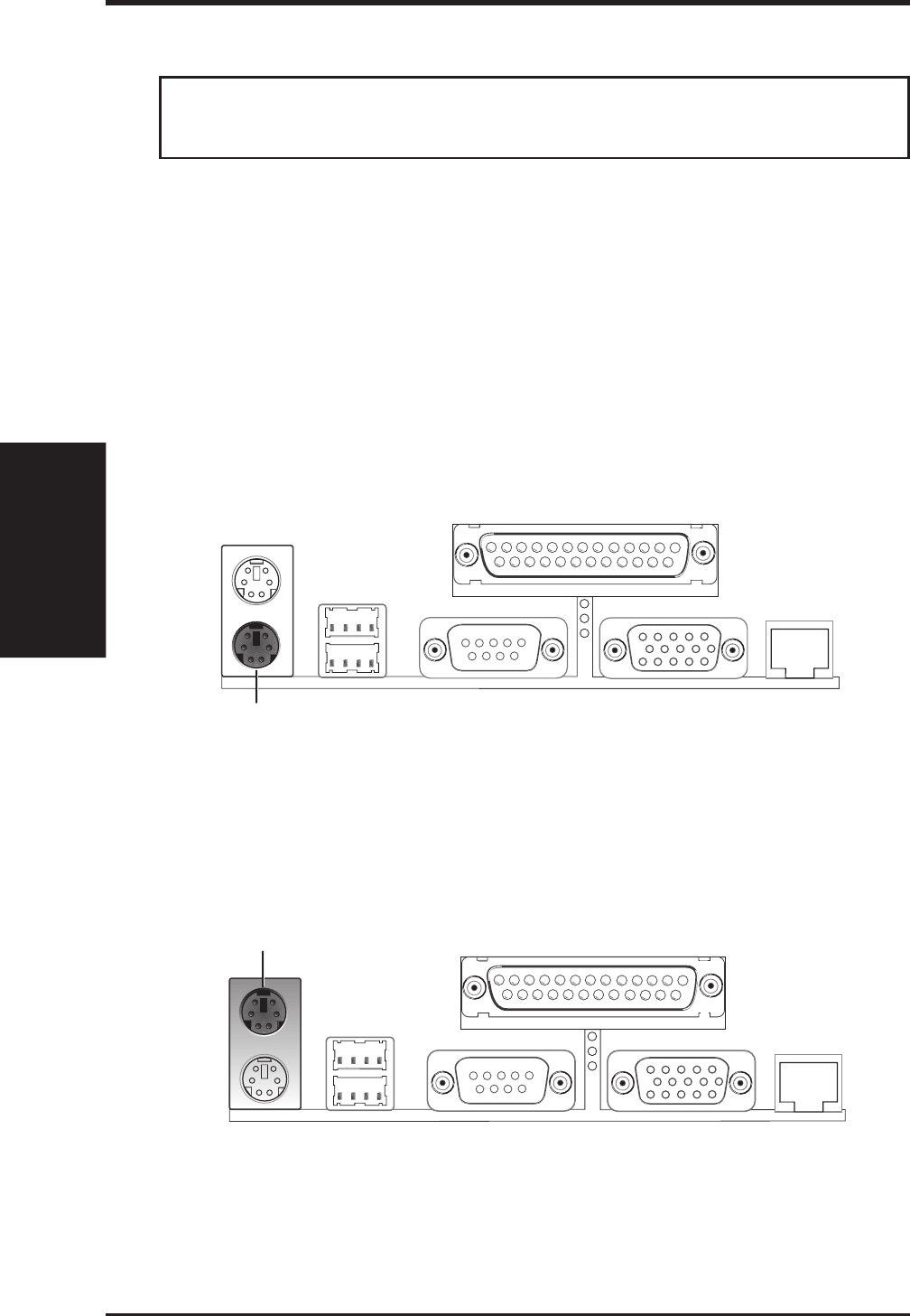
5. External Connectors
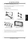
IMPORTANT: Ribbon cables should always be connected with the red stripe on the
Pin 1 side of the connector. The four corners of the connectors are labeled on the
motherboard. Pin 1 is the side closest to the power connector on hard drives and floppy
drives. IDE ribbon cable must be less than 46cm (18in), with the second drive connec-
tor no more than 15cm (6in) from the first connector.
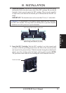
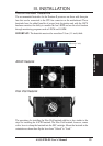
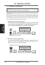
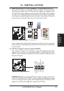
1. PS/2 Keyboard Connector (6 pin Female)
This connection is for a standard keyboard using an PS/2 plug (mini DIN). This
connector will not allow standard AT size (large DIN) keyboard plugs. You
may use a DIN to mini DIN adapter on standard AT keyboards.
PS/2 Keyboard (6 pin Female)
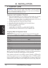
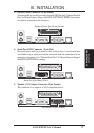
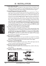
2. PS/2 Mouse Connector (6 pin Female)
The system will direct IRQ12 to the PS/2 mouse if one is detected. If not de-
tected, expansion cards can use IRQ12. See “PS/2 Mouse Function Control” in
BIOS Features Setup of the BIOS SOFTWARE.
PS/2 Mouse (6 pin Female)
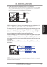
WARNING! Some pins are used for connectors or power sources. Placing jumper
caps over these will cause damage to your motherboard.